66
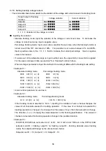
9-7-10. Setting output delay time
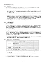
Sets the delay time of A channel :
DA
****
Sets the delay time of B channel :
DB
****
Sets the delay time of C channel :
DC
****
Sets the delay time of D channel :
DD
****
・
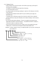
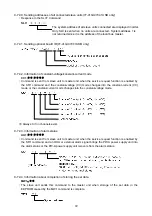
Set the delay time in the parameter
****
. The setting range of the integer type is from 0000
to 1000, which is converted into 0.0 to 10.0 seconds. The setting range is from 0.0 to 10.0.
Fragments less than 100ms are discarded.
<Precautions>
・
This command is not accepted while the MAIN OUTPUT key is turned on.
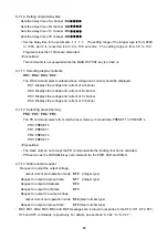
9-7-11. Selecting display contents
DS1
/
DS2
/
DS3
/
DS4
・
The DS command selects outputs whose voltage and current should be displayed.
DS1
:
Displays the voltage and current of A channel.
DS2
:
Displays the voltage and current of B channel.
DS3
:
Displays the voltage and current of C channel.
DS4
:
Displays the voltage and current of d channel.
9-7-12. Selecting preset memory
PR0
/
PR1
/
PR2
/
PR3
・
The PR command selects from which preset memory to recall data, PRESET 1 to PRESET 4.
PR0
:
PRESET 4
PR1
:
PRESET 1
PR2
:
PRESET 2
PR3
:
PRESET 3
<Precautions>
・
The slave units do not accept the PR command while the tracking function is activated.
・
PR0 serves as the VARIABLE key call command for the PWR, PAR and PAR-H.
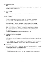
9-7-13. Status output request
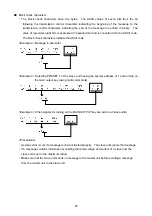
Request to output the output voltage,
output current and operation mode
:
ST0
(Integer type)
Request to output all preset data
:
ST1
(Integer type)
Request to output all statuses
:
ST2
Request to output the ID data
:
ST3
Request to output the output voltage,
output current and operation mode
:
ST4
(Real number type)
Request to output all preset data
:
ST5
(Real number type)
・
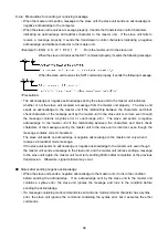
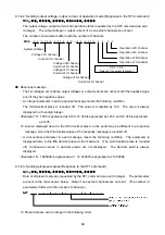
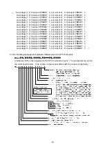
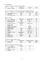
MS0, MS1, MS2, MS3, MS4 and MS5 messages are returned in response to the ST0, ST1, ST2, ST3,
ST4 and ST5 commands, respectively. For details, see sections “9-7-22.” to “9-7-27.”.

