CL-B101D40-TCRTD Manual (d0099)
Page 7
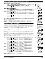
Operational Display
Sub-menu
MODE
STEP A Calibration
Mode
STEP B Calibration
Mode
STEP E
Calibrate
Analog
Output
Lo
STEP F
Calibrate
Analog
Output
Hi
Will only appear if the analog
output option is installed
To Digital Span Selection
for Bargraph Display
See Page 5
To Thermocouple
or RTD Selection
Mode See Page 4
Operational Display
TWO POINT ANALOG OUTPUT
RANGE SETTING AND CALIBRATION
+
x
–
x
4.00
+
x
–
x
20.00
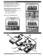
Determine if the Analog Output Selection Header is in the 4 to 20mA
(0-20mA) position or the 0 to 10VDC position. If necessary, the mod-
ule may have to be removed and the header position changed (see
Component Layout below).
Note
: Always disconnect power from the meter before removing the
analog output module to adjust the mA or Volts output selection head-
er and reinstalling it. When power is reconnected, the meter’s software
will automatically detect the presence or absence of the analog output
module.
STEP A Enter the Calibration Mode
1)
Press the
P
and buttons at the same time. Display
toggles between [cAL] and [oFF].
2)
Press the or button. Display changes from [oFF] to
[on].
3)
Press the
P
button. Display toggles between [cAL] and
[out] input calibration.
Note
: If at this point the display skips directly to toggle between
Zero and the previous Zero setting, the software is detecting that the
optional analog output hardware is NOT installed.
STEP B Enter the Two Point Analog [ouT] Output Range Setting
and Calibration Mode
1) Press the
P
button. Display toggles between [cLo] and an
internal scale factor.
STEP E Set or Calibrate [cLo] the Low Analog Value of the
Analog Output Range
1) Connect a multimeter to analog output pins 17 and 18
(see Rear Panel Pinouts on page 10). Using the and
buttons, adjust the analog output to the desired low value as
measured on the multimeter. cLo may be adjusted to any
value from –0.3 mA to 18 mA (mA output selected) or from
–0.6 V to 8 V (volt output selected). However, the output of
cLo must always be less than the value selected for chi. If a
reversed analog output is desired, the values selected to
establish the Digital Span can be reversed (see top of page
6). For digital readings outside the Digital Span selected, the
analog output will not go any lower than the calibrated value
set for cLo. However, the analog output will linearly rise
above the value set for chi, up to the the maximum analog
output capability (see chi below).
2) Press the
P
button. Display toggles between [chi] and an
internal scale factor.
STEP F Set or Calibrate [chi] the High Analog Value of the
Analog Output Range
1) Using the and buttons, adjust the analog output
to the desired high value as measured on the multimeter
display. chi may be adjusted to any value from 18 mA to
24 mA (mA output) or from 8 V to 10.3 V (volt output).
However, the value must be higher than the value select-
ed for cLo. For digital readings outside the Digital Span
selected, the analog output will linearly rise above the
value set for chi, up to the maximum analog output capa-
bility.
2) Press the
P
button. The meter exits the calibration
mode and returns to the operational display.
Note:
The analog output range established by the values selected
for cLo and chi will occur, automatically scaled, between the two
digital values selected for AnHi and AnLo. However, the analog
output can linearly rise above the chi value set for digital readings
outside the digital span selected. See Digital Span Selection on
page 6.
Two Point Analog Output Range Setting and Calibration
Two Point Analog Output Range Setting and Calibration


