Page 8
CL-B101D40-TCRTD Manual (d0099)
Operational Display
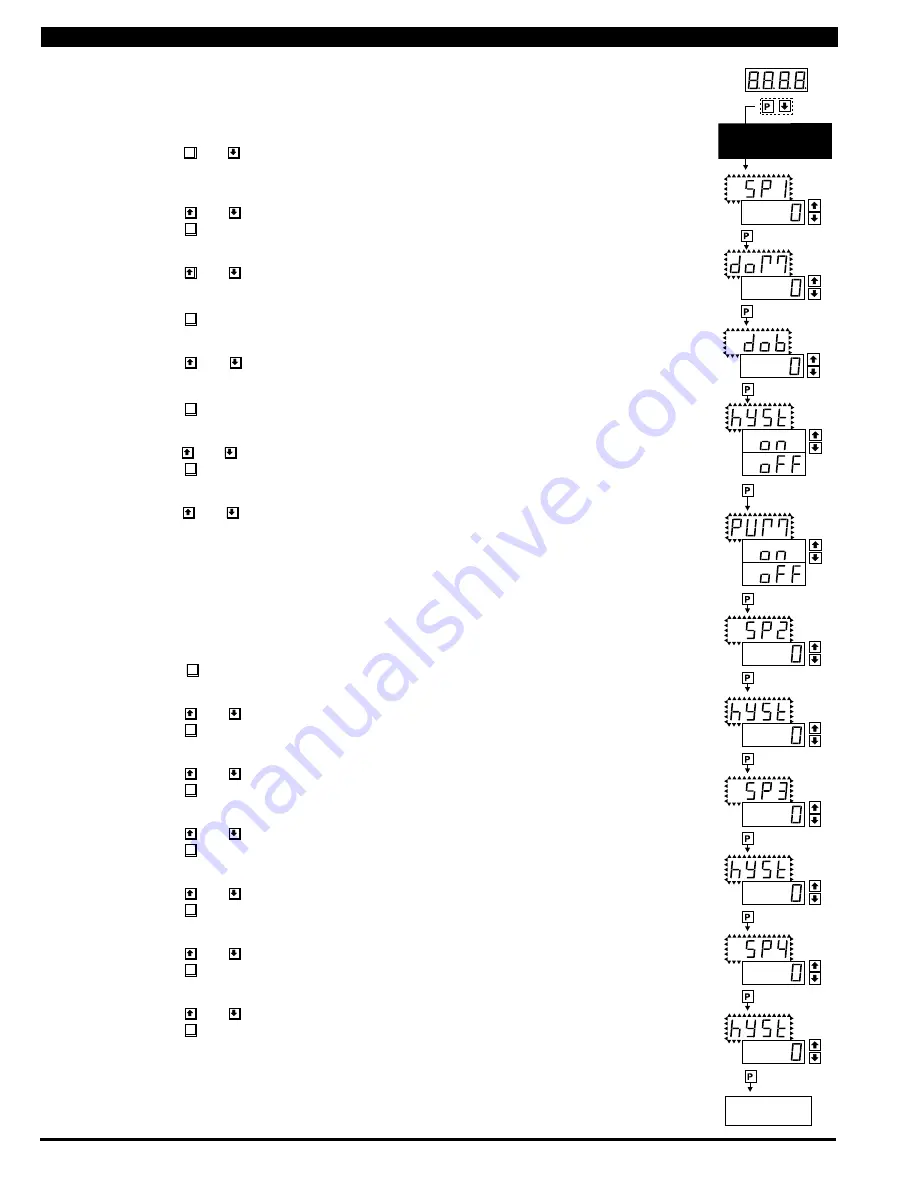
SETPOINT SETTING
AND RELAY
CONFIGURATION MODE
STEP A
STEP B
STEP C
STEP D
No [doM] or [dob]
No [doM] or [dob]
STEP E
STEP F
STEP G
STEP H
STEP I
STEP J
STEP K
STEP L
To Step M of Setpoint
Setting and Relay
Configuration Page 9
The following programming steps are required to enter the setpoint values and configure the relay functions
in a meter with four relays using four setpoints� Generally if less than four relays are installed, the setpoints
without relays are operational in software for tri-color control or display only purposes� To remove unwanted
setpoint indications, set them to 9999 or -1999 depending on the relay activation mode selected�
STEP A Enter the Setpoint Mode
1) Press the
P
and buttons at the same time� Display toggles between [SP1] and the previous
SP1 setting�
STEP B Set Setpoint 1 [SP1]
1) Using the and buttons, adjust the display to the desired SP1 value�
2) Press the
P
button� Display toggles between [doM] and the previous [doM] setting�
STEP C Set the SP1 Delay-on-Make [doM] Delay Time Setting
1) Using the and buttons, adjust the display to the desired [doM] value (0 to 9999 seconds)�
The reading must continuously remain in an alarm condition until this delay time has elapsed before
the relay will make contact (energize)�
2) Press the
P
button� Display toggles between [dob] and the previous [dob] setting�
STEP D Set the SP1 Delay-on-Break [dob] Delay Time Setting
1) Using the and buttons, adjust the display to the desired [dob] value (0 to 9999 seconds)�
The reading must continuously remain in a non-alarm condition until this delay time has elapsed
before the relay will break contact (de-energize)�
2) Press the
P
button� Display toggles between [hYSt] and the previous [hYSt] setting�
STEP E Select the Hysteresis [hYSt]
1) Using the and buttons, select the Hysteresis to be ON or OFF�
2) Press the
P
button� Display toggles between PUM and (on) or (oFF)�
STEP F Select Pump [PUM] (on) or (oFF)
1) Using the and buttons, select the Pump to be ON or OFF� When PUM is selected ON, and
SP2 is set at a value higher than SP1, the SP1 relay will operate in a special "pump on pump off" mode�
SP2 acts as the upper limit and SP1 acts as the lower limit of the Hysteresis Band on the SP1 relay�
For filling applications:
[rLYS] should be set to [LhXX] (see step M)� The SP1 relay and SP1 LED Annunciator will then activate for inputs
less than the SP1 setpoint, and remain ON until the SP2 setpoint is reached�
For emptying applications:
[rLYS] should be set to [hhXX] (see step M)� The SP1 relay and SP1 LED Annunciator will then activate for inputs
greater than the SP2 setpoint, and remain ON until the SP1 setpoint is reached�
2) Press the
P
button� Display toggles between [SP2] and the previous SP2 setting�
STEP G Set Setpoint 2 (SP2)
1) Using the and buttons, adjust the display to the desired SP2 value�
2) Press the
P
button� Display toggles between [hySt] and the previous [hySt] setting�
STEP H Select the Hysteresis [hYSt]
1) Using the and buttons, select the Hysteresis to be ON or OFF�
2) Press the
P
button. Display toggles between [SP3] and the previous [SP3] setting.
STEP I Set Setpoint 3 (SP3) (No [doM] or [dob])
1) Using the and
buttons, adjust the display to the desired SP3 value.
2) Press the
P
button� Display toggles between [hySt] and the previous [hySt] setting�
STEP J Select the Hysteresis [hYSt]
1) Using the and buttons, select the Hysteresis to be ON or OFF�
2) Press the
P
button� Display toggles between [SP4] and the previous [SP4] setting�
STEP K Set Setpoint 4 (SP4) (No [doM] or [dob])
1) Using the and buttons, adjust the display to the desired SP4 value�
2) Press the
P
button� Display toggles between [hySt] and the previous [hySt] setting�
STEP L Select the Hysteresis [hYSt]
1)
Using the and buttons, select the Hysteresis to be ON or OFF�
2) Press the
P
button� Display toggles between [rLYS] and the previous relay setting�
Please Continue On Next Page.
Setpoint Setting and Relay Configuration Mode


