Texmate, Inc. Tel. (760) 598-9899
Page 10
3/31/00 DI-45U Data Sheet (DI2)
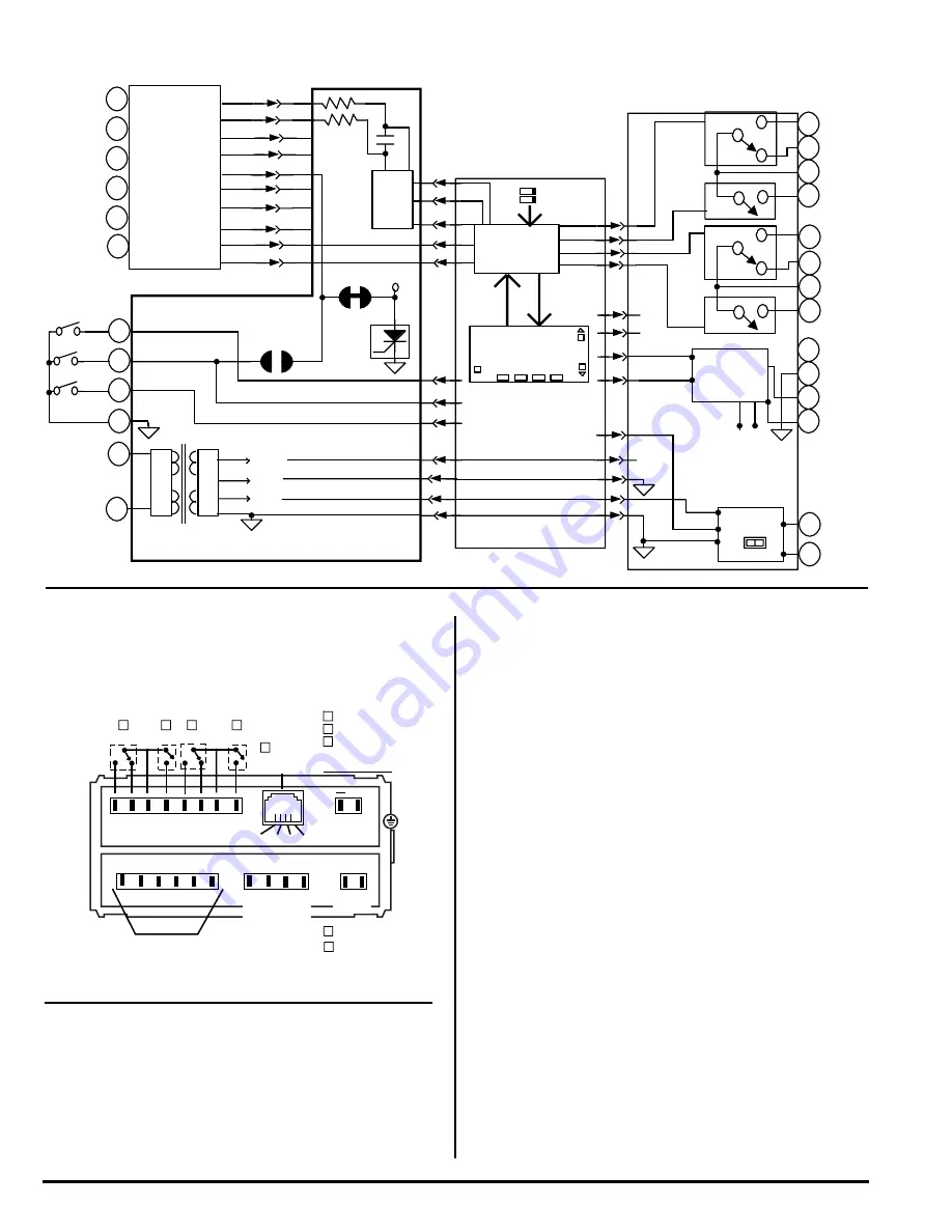
FUNCTIONAL DIAGRAM
CONNECTOR PINOUTS
The Texmate Model DI-45U TIGER CUB comes standard with
screw terminal block connections.
PIN DESCRIPTIONS
Pins 1 to 6 - Input Module. See the individual data sheet of the
input module selected for detailed information these pins or
pages 13-15 of this document. Usually Pin 1 is the Signal Input
High pin and Pin 3 is the Signal Input Low pin.
Pin 8 - Program Lock. By connecting this pin to the Common
Pin 11, the set up program is locked out. The programmed
meter parameters may be viewed but not changed, when the
meter is in the "locked out" mode.
Pin 9 - Hold Reading. When this pin is connected to the
Common Pin 11, the reading displayed will be frozen. A/D conver-
sions will continue however, and as soon as Pin 9 is disconnected
from Pin 11 the updated reading will be instantly displayed.
Pin 10 - Display Test. When this pin is momentarily connected
to the Common Pin 11, all segments of the display light up and
five 8's are displayed for 3 seconds. This detects any missing
segments in the display. The microprocessor is also reset dur-
ing the 3 seconds.
Pin 11 - Common. To activate, Hold, Test, Lockout or Reset, the
respective pins have to be connected to this Common Pin.
Pin 14 & 15 - AC Power Input. These pins are the power input
pins of the meter. The standard DI-45U TIGER CUB is precon-
figured for 100/120VAC for meters sold in North America. To
reconfigure for 200/240VAC operation, remove the meter from
the case and pull out the AC Power Voltage Selector located
directly behind the transformer on the printed circuit board. Turn
the AC Power Voltage Selector around and reinsert it into the
socket so that "200/240VAC" is visable. See the Component
Layout on page 10.
Chassis Ground Tab - This grounding tab is supplied for chas-
sis grounding.
POWER SUPPLY
The standard power supply for the DI-45U TIGER CUB is 100
to 120VAC or 200 to 240VAC, user selectable. See the Pin Out
Descriptions for Pins 14 and 15 for more details.
GND
30
23
29
24
25
27 26
28
17 16
19
20
18
SERIAL OUTPUT
OPTIONAL SETPOINT RELAYS
21
Lo1
Lo2
Hi1
Hi2
+
Logic
ANALOG OUT
(Non-Isolated)
(Non-Isolated)
200-240 VAC
100-120 VAC
14 15
AC
POWER
for display range
0 to 10 VDC
0 to 20 mA
4 to 20 mA
HOLD
TEST
LOCK
COMMON
11
9
10
8
4
5
6
2
3
1
INPUT PINS (DEPENDS
ON SPECIFIC
MODULE SELECTED)
47K
47K
COM
NO
COM
NO
COM
NC
1
2
3
4
5
6
7
+5V DC
-5V DC
I/O 1
I/O 2
INPUT
MODULE
Input Module
+24V DC
8
9
10
11
14
15
Display Test
Micro Reset
Common
+5V DC
- 5V DC
+24VDC
GND
MAIN BOARD
DISPLAY BOARD
GND
MicroProcessor
8.8.8.8.8
OPTIONAL OUTPUT BOARD
Form C
Logic Level TTL
Serial Output
Analog
Lo1
Lo2
See specific
Input Lo
Input Hi
or HOLD
1
2
3
4
5
6
Program and
Setpoint Lock
Switches
Hi1
Hi2
10A
Form C
10A
5A
Form A
5A
Form A
23
24
25
26
27
28
29
30
21
20
19
18
17
16
Output
Volts
mA
0.01
GND
GROUND
RXD
TXD
+5V -5V
GND
NORMALLY
NORMALLY
NORMALLY
OPEN Lo1
CLOSED Lo1
COMMON Lo
OPEN Lo2
NORMALLY
NORMALLY
NORMALLY
OPEN Hi1
CLOSED Hi1
COMMON Hi
OPEN Hi2
_
ANALOG
OUTPUT
Program Lock
Reading Hold
There are Input Modules
for almost any input signal.
Input Pins vary for different
modules, so please
for connection Details
Data Sheets
A/D
Converter
Crowbar
Protection
Circuit for
Over
voltage
+24V
J1
J2
Internal Header Pins
and EEPROM
Prog
Alarm
Annunciators
Front Panel
Push Buttons
NO
NO
COM
NC
8
9
10
GND
REFERENCE HI
REFERENCE LO
L2 L1 H1 H2
+5VDC
AC POWER
SELECTOR
RECTIFIER &
REGULATOR


