Texmate, Inc. Tel. (760) 598-9899
Page 12
3/31/00 DI-45U Data Sheet (DI2)
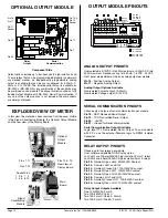
OPTIONAL OUTPUT MODULE
OUTPUT MODULE PINOUTS
RELAY OUTPUT PINOUTS
Choose up to four relays per module.
User software selectable NO/NC relay status.
LoL1/HiL1 are 10Amp/240VAC high insulation Form C relays.
LoL2/HiL2 are 5 Amp/240VAC high insulation Form A relays.
Pin 23 - Normally Open HIL2. 5A/240VAC Contact.
Pin 24 - Common HIL1 and HIL2
Pin 25 - Normally Closed HIL1. 10A/240VAC contact.
Pin 26 - Normally Open HIL1. 10A/240VAC contact.
Pin 27 - Normally Open LOL2. 5A/240VAC contact.
Pin 28 - Common LOL1 and LOL2
Pin 29 - Normally Closed LOL1. 10A/240VAC contact.
Pin 30 - Normally Open LOL1. 10A/240VAC contact.
Relay Output Outputs Available
One 10A/240VAC Form C
Two 10A/240VAC Form C
Two 10A Form C/One 5A Form A
Two 10A Form C/Two 5A Form A
30
23
29
24
25
27 26
28
17 16
19
20
18
OPTIONAL SETPOINT RELAYS
21
+
ANALOG OUT
(Isolated)
SERIAL OUTPUT
RS232
RS485
(Isolated)
18 to 36 VAC
9 to 60 VDC
85 to 265 VAC
95 to 370 VDC
Lo1
Lo2
Hi1
Hi2
for display range
0 to 10V
0 to 20mA
4 to 20mA
GND
HOLD
TEST
LOCK
COMM
11
9
10
8
14 15
AC/DC
POWER
ANALOG OUTPUT PINOUTS
Pin 16 - Positive Analog Output
Pin 17 - Negative Analog Output
Analog Output Options Available
Non-Isolated Current output (0-20mA)
Non-Isolated Voltage output (0-10VDC)
User selectable 0-10VDC into 5K
Ω
maximum or 0-20mA DC into
500
Ω
maximum. Desired scaling for 4-20mA, 1-5VDC, 0-1VDC.
Front panel programmable. Only one analog output per module.
Pin 18 - RXD. Received Serial Output
Pin 19 - TXD. Transmitted Serial Output
Pin 20 - +5VDC.
Pin 21 - Ground for Serial communication
Serial Communication Output Available
Logic level TTL Non-isolated Serial Output. To communicate
with PC’s, use the external Texmate logic to RS232 Isolated
Converter.
SERIAL COMMUNICATION PINOUTS
Choose only one type of serial communication per module.
Component Side
Output options include up to four heavy duty, high isolation 5 and
10 amp relays that can be programmed individually to operate in
any desired manner. An independently programmable analog
output is available that can be user configured for 4-20mA, 0-
20ma or 0 to 10VDC. The isolated serial output is available as
RS-232C or RS-485. All or any combination of these options may
be combined on one module. The above illustration shows a fully
loaded Output Module with RS-232C Serial Communication. If
any one of the output options is not included, the components
are simply not placed.
Main
Board
Rear View of
Display Board
Pins 1-11
Pins 1-10
Signal
Conditioning
Module
1 3 5 7 9
2 4 6 8 10
Pins 12 & 13
Optional
Output
Module
Socket Pins
In this view, the meter has been removed from the case. Visible
is the Signal Conditioning Module, the Optional Output Module
and the rear view of the Display Board.
EXPLODED VIEW OF METER
Analog Output
Relay
Output
Serial
Communication
S
o
cke
t
RJ-11
Socket
Pin 16
Pin 17
Pin 23
Pin 30
Pin 13 &
Pin 12
Socket
Pin 11
Pin 1


