Page 21
6/23/04 DI-50B51 320 Series (NZ306)
Texmate, Inc. Tel. (760) 598-9899
•
www.texmate.com
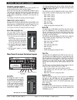
0 No function
1 On Demand TARE from the PROGRAM button
2 On Demand Single-point Calibration from the PRO-
GRAM button (requires single input source)
3 On Demand Two-point Calibration from the PRO-
GRAM button (requires dual input source)
4 On Demand Primary Input Compensation Mode
from the PROGRAM button
5 On
Demand
Manual
Loader
Mode
(no
increase/decrease with HOLD active)
6 -
7 -
Note:
When settings 1 to 5 are programmed a decimal point
appears at the right of the display while the meter is in the
operational display. To activate the function, while in the
operational display, press the PROGRAM button for 4
seconds.
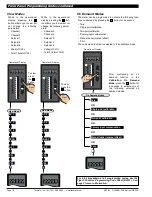
The Tiger 320 Series meter has an extremely powerful set of
input and output calibration modes. See Diagram below.
Functions Activated by
Button Mode
In this mode the meter can be programmed to activate one of
the following on demand functions by pressing the
button
while in the operational display:
•
On Demand TARE.
•
On Demand Single-point Calibration (requires single input source).
•
On Demand Two-point Calibration (requires dual input source).
•
On Demand Primary Input Compensation Mode.
•
On Demand Manual Loader Mode.
P
P
0 Functions Activated
by Pressing the PRO-
GRAM Button
1 Calibration Procedures
2 Related
Calibration
Functions
3 -
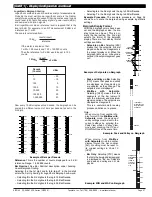
CALIBRATION MODES FOR INPUT AND OUTPUT
FIRST DIGIT
SECOND DIGIT
0 Manual Calibration
(requires NO input source)
1 Two-point Calibration (requires dual input source)
2 Calibrate Thermocouple (requires K type thermo-
couple input source)
3 Calibrate RTD (requires RTD 385 input source)
4 Calibrate Smart Input Module.
Note: This function is
not available on all input modules
5 Calibrate Analog Output (requires multimeter con-
nected to pins 16 and 17)
6 -
7 -
0 Serial Communications Properties
1 Set Auto Zero Maintenance for 3rd digit
2 Set Averaging Samples & Averaging Window for 3rd
digit
3 Set K Factor & Cutoff for Totalizer
4 Setup 32-point Linearization Tables
5 Scale Analog Output
6 -
7 -
See
I-Series Input Modules Guide (Z87)
for details
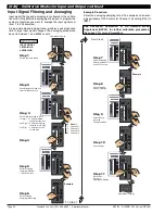
Press the PROGRAM button for 4
seconds to tare the selected channel
P
P
4 secs
P
4 secs
P
4 secs
P
4 secs
Auto zero capture band
OBJECT FOR 2nd DIGIT
0
Result
1
Channel 1
2
Channel 2
3
Channel 3
4
Channel 4
5
-
6
-
7
-
THIRD DIGIT
0
-
1
Analog Output 1
2
Analog Output 2
3
-
4
-
5
-
6
-
7
-
THIRD DIGIT
0
-
1
Analog Output 1
2
Analog Output 2
3
-
4
-
5
-
6
-
7
-
THIRD DIGIT
0
-
1
Total 1
2
Total 2
3
-
4
-
5
-
6
-
7
-
THIRD DIGIT
Note: The correct input sig-
nal channel must be selected
in the 3rd digit when config-
uring a linearization table
using the auto setup mode.
Calibration Modes
The following calibration modes are available:
•
Manual Calibration (requires NO input source).
•
Two-point Calibration (requires dual input source).
This is the calibration mode generally used to calibrate the meter for
most applications. An example procedure has been included.
•
Calibrate Thermocouple (requires K type thermocouple
input source).
•
Calibrate RTD (requires RTD 385 input source).
•
Calibrate Smart Input Module (not available on all input
modules).
•
Calibrate Analog Output (requires multimeter connected to pins
16 and 17).
Use
buttons to ADJUST primary input compen-
sation value from
–
19999 to 99999 on CH1 to CH4 ONLY
Use
buttons to ADJUST manual loader output
(via analog output 1 or 2) value from
–
19999 to 99999
[
C
A
L
]
-
C
ali
b
r
ati
o
n
M
o
d
e
s
f
o
r
I
npu
t
a
nd
O
u
t
pu
t


