Page 59
6/23/04 DI-50B51 320 Series (NZ306)
Texmate, Inc. Tel. (760) 598-9899
•
www.texmate.com
I
NPUT
M
ODULE
C
OMPONENT
G
LOSSARY
Z
E
R
O
A
D
J
U
S
T
H
e
a
d
e
r
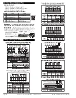
When this header is provided, it works in conjunction
with the ZERO OFFSET RANGE Header, and expands
the ZERO pot
’
s offset capability into five equal negative
steps or five equal positive steps. This enables virtual-
ly any degree of input signal offset required to display
any desired engineering unit of measure.
Z
E
R
O
OFF
S
E
T
RA
N
G
E
H
e
a
d
e
r
When provided, this three position header increases
the ZERO pot
’
s capability to offset the input signal, by
±
25% of the full scale display span. For example a
Negative offset enables a 1 to 5 V input to display 0
to full scale. The user can select negative offset, pos-
itive offset, or no offset (ZERO pot disabled for two
step non-interactive span and offset calibration).
S
P
A
N
RA
N
G
E
H
e
a
d
e
r
When this header is provided it works in conjunction
with the SPAN ADJUST Header by splitting its adjust-
ment range into a Hi and a Lo range. This has the effect
of dividing the adjustment range of the SPAN pot into ten
equal 10% steps across 100% of the input Signal Span.
I
N
P
UT
RA
N
G
E
H
e
a
d
e
r
s
Range values are marked on the PCB. Typically two to
eight positions are provided, which are selected with
either a single or multiple jumper clip. When provided,
a custom range position is only functional when the
option has been factory installed.
I
npu
t
a
nd
O
u
t
pu
t
P
i
n
s
On most modules Pin 1 is the Signal High input and
Pin 3 is the Signal Low input. Typically Pin 2 is used
for Excitation Voltage output.
24
V
DC
O
u
t
pu
t
f
o
r
4
-
20
m
A
H
e
a
d
e
r
On some modules this header enables a 24 V DC 25 mA
(max) Excitation/Auxiliary output to be connected to Pin
2 that can power most 4-20 mA transmitters.
LO RANGE
HI RANGE
10%
SPAN Pot %
10%
10%
10%
10%
10%
Signal Span %
20%
30%
40%
50%
1
SPAN Adjust
Header position
Span Adjust Header
Span Adjust Header
Span Range Header
2
3
4
5
10%
10%
10% 10%
10%
60%
70%
80% 90%
100%
1
2
3
4
5
< Decrease Span Increase >
1 2
3
4 5
< Decrease Span Increase >
1 2
3
4 5
Equivalent
Circuit
Acts like a
150 Turn
Potentiometer
Low Range
High Range
Input LO
Input HI
HI
LO
< Increase Zero Decrease >
5 4
3
2 1
<
Incr
eas
e Z
ero
De
crea
se >
5
4
3
2
1
SPAN
Turn Clockwise to
Increase Reading
To the
Right Rear
HI
LO
24V
Exc
Offset
0
—
+
0
—
+
Custom
200V
20V
2V
600V
200V
O
N
O
FF
OFF
ON
2
4
V
E
X
C
< Increase Span Decrease >
5 4
3
2 1
<
Incr
eas
e S
pan
De
crea
se >
5 4
3
2 1
R
a
n
g
e
HI
LO
HI
LO
Zero Offset
Range Header
Zero Adjust Header
CALIBRATE position, Zero Pot disengaged (no offset applied)
Zero Adjust Header
+
–
ZERO Pot Span
NEGATIVE OFFSET
POSITIVE OFFSET
Offset Range
ZERO Adjust
Header Position
5
6400
-25200
to
-31600
4
6400
-18900
to
-25300
3
6400
-12600
to
-19000
2
6400
-6300
to
-12700
1
6400
0
to
-6400
6400
0
to
+
6400
1
6400
+
6300
to
+
12700
2
6400
+
12600
to
+
19000
3
6400
+
18900
to
+
25300
4
6400
+
25200
to
+
31600
5
< Increase Zero Decrease >
5 4
3
2 1
< Decrease Zero Increase >
1 2
3
4 5
+
0
–
ZERO
Turn Clockwise to
Increase Reading
To the
Left Rear
S
P
A
N
P
ot
e
n
ti
o
me
t
e
r
(
P
ot
)
If provided, the 15 turn SPAN pot is always on the
right side (as viewed from the rear of the meter).
Typical adjustment is 20% of the input signal range.
15 Turn Potentiometer
≈
+
5%
≈
–
5%
–
0
+
20%
SPAN Pot %
20%
20%
20%
20%
20%
Signal Span %
40%
60%
80%
100%
1
SPAN Adjust
Header position
2
3
4
5
< Decrease Span Increase >
1 2
3
4 5
Acts like 75 Turn 1 Megaohm Potentiometer
Input LO
Input
HI
Equivalent
Circuit
S
P
A
N
A
D
J
U
S
T
H
e
a
d
e
r
This unique five-position header expands the adjustment
range of the SPAN pot into five equal 20% steps, across
100% of the input Signal Span. Any input Signal Span can
then be precisely scaled down to provide any required
Display span from full scale to the smallest viewable unit.
Z
E
R
O
P
ot
e
n
ti
o
me
t
e
r
(
P
ot
)
If provided, the ZERO pot is always to the left of the
SPAN pot (as viewed from the rear of the meter).
Typically it enables the input signal to be offset
±
5%
of the full scale display span.
J / T
J
R
0
–
+
Sensor
Break
Detect
O
N
O
FF
4W
6W
OFF
ON
F
un
c
ti
o
n
S
e
l
e
c
t
H
e
a
d
e
r
s
On some modules various functions such as Amps and
Volts, 4 wire and 6 wire, or cold junction compensation are
selected by header positions that are marked on the PCB.
10V
5V
10V
5V
EXT
EXC
EXC
E
x
c
i
t
ati
o
n
O
u
t
pu
t
S
e
l
e
c
t
H
e
a
d
e
r
s
When excitation outputs are provided, they are typi-
cally 5 V DC max 30 mA, 10 V DC max 30 mA (300
Ω
or higher resistance) or external supply. They are
selected by either a single or multiple jumper clip.
Zero Offset Range Header
0 +
–
No
Offset
NEGATIVE OFFSET
Decreases Digital Reading
POSITIVE OFFSET
Increases Digital Reading
15 Turn Potentiometer
–
0
Equivalent
Circuit
15 Turn Potentiometer
+
0
Zero Pot
Disabled
≈
–
25%
Offset Range
–
100% of Offset
ZERO Pot%
≈
+
25%
+ 100% of Offset
Du
a
l
i
nput modu
l
e
s
,
a
nd thos
e
modu
l
e
s
e
xc
l
us
i
v
e
l
y comp
a
t
i
b
l
e
w
i
th th
e
L
e
op
a
rd or T
i
g
e
r
Fa
m
ili
e
s
,
do not h
a
v
e
z
e
ro
a
nd
sp
a
n
a
d
j
ustm
e
nts
.
Th
e
s
e
modu
l
e
s
a
r
e
sc
a
l
e
d
a
nd c
a
li
br
a
t
e
d us
i
ng th
e
i
nt
e
rn
a
l
softw
a
r
e
funct
i
ons of
ea
ch
i
nd
i
v
i
du
a
l
m
e
t
e
r
.
I
-
S
e
r
i
e
s
I
npu
t
Sig
n
al
C
o
nd
i
ti
o
n
i
n
g
M
o
du
l
e
s
c
o
n
ti
nu
e
d
I
-
S
e
r
i
e
s
I
npu
t
Sig
n
al
C
o
nd
i
ti
o
n
i
n
g
M
o
du
l
e
s
c
o
n
ti
nu
e
d


