background image

Page 6

FL-B101D40PF Power factor (D0109) Manual

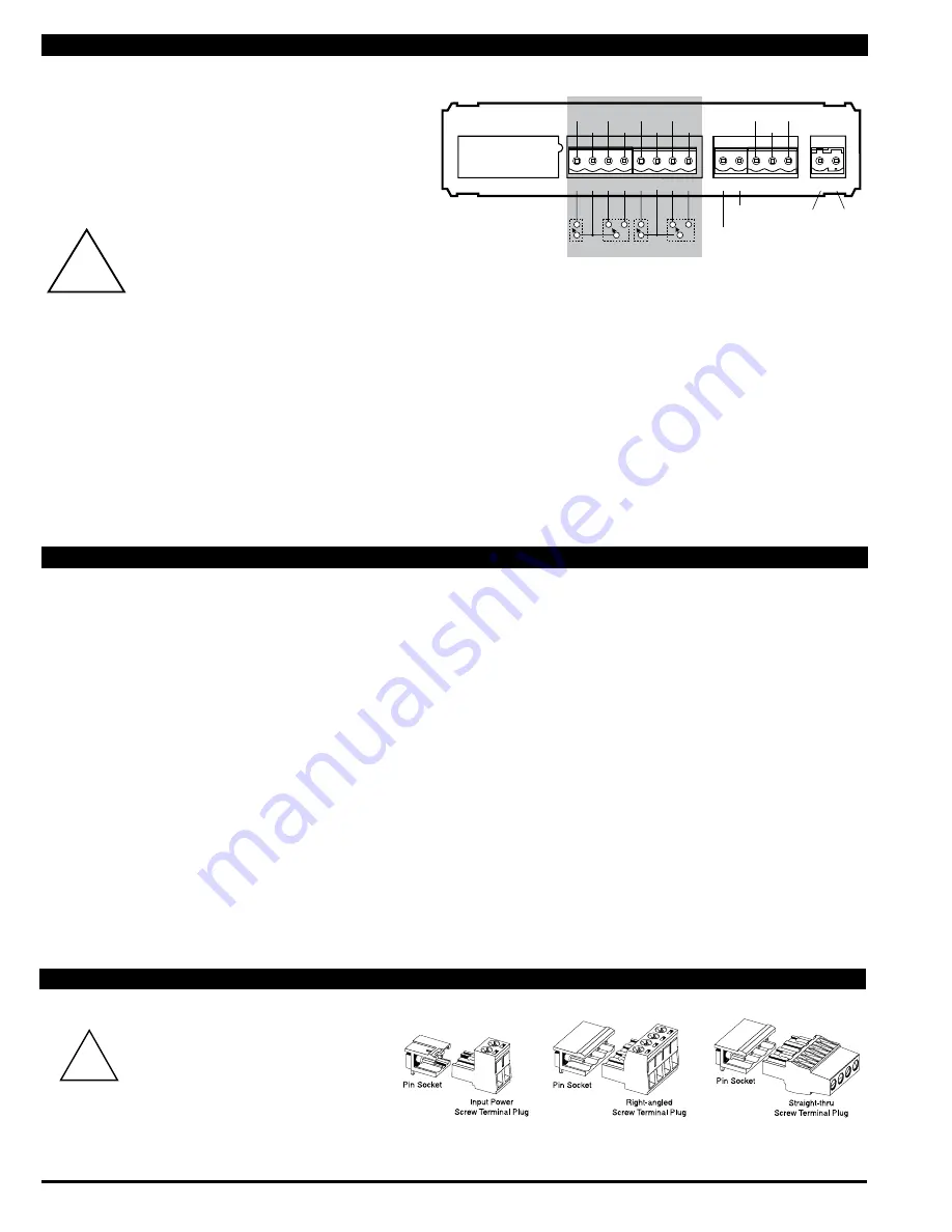
Standard plug-in screw terminal blocks provided by Texmate:

WARNING

AC and DC input signals and power 

supply voltages can be hazardous. 

Do Not connect live wires to ter-

minal blocks, and do not insert, 

remove or handle terminal blocks with live 

wires connected.

!

Connectors

!

WARNING

AC and DC input signals and power supply 

voltages can be hazardous. Do Not connect live wires to 

screw terminal plugs, and do not insert, remove or handle 

screw terminal plugs with live wires connected.

SP3

NO

SP1/3

COM

SP1

NC

SP1

NO

SP4

NO

SP2/4

COM

SP2

NC

SP2

NO

LOCK

COMM

DIM

SP3

SP4

SP1

COM 1&3

NO3

NC1

COM 2&4

NC2

NO4

NO1

NO2

SP2

8 9 10 11 12 13 14 15

17 18 19 20 21

23 24

1-6

Input Signal 

Conditioning Moduls

Analog

Analog

Output –

AC

Neutral

AC 

Line

– DC

+ DC

or

This meter uses plug-in type screw terminal connectors for all 

input  and  output  connections.  The  power  supply  connections 

(pins 23 and 24) have a unique plug and socket outline to prevent 

cross  connection.  The  main  board  uses  standard  right-angled 

connectors.
Replacement  2-,  3-,  and  4-pin  plug  connectors  are  available 

(see Accessories


on page 10).

Input Signal – Pins 1 to 6 

Pins 1 to 6 are reserved for the input signal conditioner. 

See the data sheet for the selected input signal conditioner. 

Pins 17 to 21 – Rear Panel Switches

Pin 19  Programming LOCK. By connecting the LOCK pin  


to the COMMON pin, the meter's programmed  


parameters can be viewed but not changed.

Pin 20  COMMON. To  activate the LOCK or DIM functions  


from the rear of the meter, the respective pins have  


to be connected to the COMMON pin. This pin is  


connected to the internal power supply ground.

Pin 21  DIM. By connecting the display dim (DIM) pin to 


the COMMON pin, the display brightness setting


is halved.

Pins 23 and 24 – AC/DC Power Input

Auto-sensing AC/DC power supply. For voltages between 


85-265 V AC / 95-300 V DC (PS1) or 18-48 V AC / 10-72 V 

DC (PS2).

Pin 23  AC Neutral / –DC. Neutral power supply line.

Pin 24  AC line / +DC. Live power supply line.

Connector Pinouts

Pin Descriptions

Note:  Gray shaded area is not applicable to this model.

Summary of Contents for Leopard Series

Page 1: ...or Bargraph Indicator Bargraph center zero function Digital display blanking Four level brightness control accessed by the button and adjusted by the button Software Features Bargraph Center Point Display Mode Selection 5 Case Dimensions 9 Component Layout 7 Connector Pinouts 6 Connectors 6 Controls and Indicators 2 Decimal Point and Brightness Selection 5 Software Features 1 Software Logic Tree 3...

Page 2: ...at an alternative logic branch will be followed when a particular option is present When two buttons are shown side by side and enclosed by a dotted line they must be pressed at the same time then released to go onto the next programming step If an X appears through a digit it means that any number displayed in that digit is not rel evant to the function being explained P Span 10000 P P When the a...

Page 3: ...ut Lo cLo will occur This branch will only appear if the analog output option is installed DIGITAL SPAN SELECTION FOR ANALOG RANGE OUTPUT See Page 6 DIGITAL DISPLAY ON OFF See Page 5 BARGRAPH CENTER POINT DISPLAY MODE SELECTION See Page 6 TWO POINT ANALOG OUTPUT RANGE SETTING AND CALIBRATION See Page 7 Set the Decimal Point dp Select XX XX Bargraph Display Scale Lo Range Setting bLo Adjust to 50 B...

Page 4: ...Digital Span Selection for Bargraph Display and the display flashes bhi and the previous setting ERROR Indicates Unsuccessful Calibration If the calibration was unsuccessful the display indicates Err the new calibration settings just entered will not take effect and the previously stored setting will remain The three most likely causes of an error during calibration are 1 The full scale and zero s...

Page 5: ...ous brightness setting STEP D Set the Bargraph and Digital Display Brightness 1 Using the and buttons adjust the display to the desired brightness setting 4 is the brightest setting 2 Press the P button Display toggles between Cto and oFF Digital Span Selection For Bargraph Display Decimal Point and Brightness Selection Bargraph Center Point Display Mode Selection STEP G Bargraph Center Point Mode...

Page 6: ...a unique plug and socket outline to prevent cross connection The main board uses standard right angled connectors Replacement 2 3 and 4 pin plug connectors are available see Accessories on page 10 Input Signal Pins 1 to 6 Pins 1 to 6 are reserved for the input signal conditioner See the data sheet for the selected input signal conditioner Pins 17 to 21 Rear Panel Switches Pin 19 Programming LOCK B...

Page 7: ...ODULE 24V Exc IP07 Universal Process Input 2V 5V 10V 20V 200V 2mA 20mA Custom Custom 20mA 2mA 200V 20V 10V 5V 2V VOLTAGE CURRENT UNIVERSALPROCESS Processinput Requires Digital Calibration HI LO OFF ON 24VEXC 224C Input Range Header IP07 24V Exc on off Header Signal Type Header Voltage Current ...

Page 8: ...l adapter enables modern DIN meters to fit in existing cutouts individually or stacked when replacing old 6 edgewise mechanical pointer meters Fits existing cut outs for 6 150 mm edgewise switchboard pointer meters from Crompton G E Westinghouse Yokogawa and most others Width 43 7 mm to 48 mm 1 72 to 1 89 Height 143 4 mm to 149 mm 5 62 to 5 88 Fits 6 Edgewise Pointer Meter Cut Outs Panel Adapter W...

Page 9: ... IO board The adapter snaps on the 36x144 mm 1 42 x5 69 case and enables single unit or stack mounting in an existing 6 edgewise pointer meter cut out 100 0 25 50 75 100 0 25 50 75 SP1 SP2 SP3 SP4 Zero Span Zero Span Panel adaptor plates are available to retrofit most existing panel cutouts 31mm 1 22 These dimensions are increased by 2mm 0 08 when the metal surround case is installed For extra str...

Page 10: ...odel number FL B101D40PF 144x36mm 101 Segment Bargraph 4 Digit Scale Factor Standard Options for this Model Number Order Code Suffix Description Display VRR Red LED Bargraph w 4 Digit Red DPM Vertical VGG Green LED Bargraph w 4 Digit Green DPM Vertical VGR Green LED Bargraph w 4 Digit Red DPM Vertical VRG Red LED Bargraph w 4 Digit Green DPM Vertical HRR Red LED Bargraph w 4 Digit Red DPM Horizont...

Reviews: