Texmate, Inc. Tel. (760) 598-9899 • www.texmate.com
Page 6
FX-B101Q-DCA_DCV manual (d0103)
For example: the three steps to obtain an Analog Output of 4mA to 20mA for an input of
0 to 10V are:
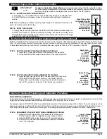
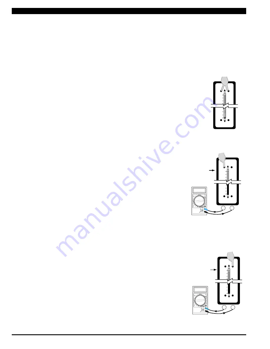
STeP A ReSeT THe ANAlOg OuTPuT SCAlINg
1) Press the LO and HI buttons simultaneously and hold them down for 2
seconds. This will reset the analog output scaling to the default value. The
default analog output scaling is approximately 0 to 20mA (0 to 10V if voltage
output option is selected) for an input that is 0 to 100% of the range select-
ed on the input signal conditioner.
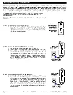
STeP B CAlIBRATe ANAlOg OuTPuT FOR lO SIgNAl
1) Apply the low input signal (0V in this example) to the meter.
2) Connect an external multimeter to the analog output pins (Pins 17 and 18).
3) Using the LO button adjust the analog output as measured on the external
multimeter to be the required value. (4mA in this example). When the LO
button is pressed, the UP or DOWN indicator LED shows the direction of
change. To reverse the direction of change release the LO button and press
down again. Initially the output changes very slowly, but speeds up as the
LO button remains pressed down. The analog output for a low input can be
set in this step to any value in the range of 0 to 20mA or 0 to 10V ( if the
voltage output option is selected).
STeP C CAlIBRATe ANAlOg OuTPuT FOR HI SIgNAl
1) Next apply the high input signal (10V in this example) to the meter.
2) Using the HI button, adjust the analog output as measured on the external
multimeter to be the required value. (20mA in this example). When the HI
button is pressed the UP or DOWN indicator LED shows the direction of
change. Release the HI button and press again to reverse the direction of
change. Initially the output changes very slowly, but speeds up as the HI
button continues to remain pressed. This output may be higher or lower
than the value set in Step 2, and may be any value in the range of 0 to 20mA
or 0 to10V. This allows the easy reversal of analog output that is required in
some applications.
Apply 0 V
to the Input
Signal Pins
+
–
Adjust the Analog
output to 4.00mA
17
18
4.00
100
0
Zero
Span
Lo
Hi
ANALOG OUTPUT
Apply 10 V
to the Input
Signal Pins
Adjust the Analog
output to 20.00mA
17
18
20.00
+
–
100
0
Zero
Span
Lo
Hi
ANALOG OUTPUT
When the optional analog output module is installed, an independently calibrated 16 bit isolated, voltage or current analog output is
available. The analog signal is independently scaled to the input signal and not to the bargraph display. It is important to note
that the Analog Output is completely independently of the bargraph display. This means for example that the bargraph display may
be scaled to go from zero to full scale as the input changes from 0 to 5V, while at the same time, the analog output is scaled to go
from 4 to 20mA as the input changes from 2 to 3V. Rescaling the bargraph or the analog output will not affect the scaling of the other.
To calibrate the Analog Output you must be able to input two input signals. Usually
the minimum input (LO Input) and the maximum (HI Input) signals are used for
maximum accuracy.
Analog Output Scaling and Calibration
100
0
Zero
Span
Lo
Hi
ANALOG OUTPUT
Reset the analog
ouput scaling by
pressing the LO
and HI buttons
simultaneously
for 2 secs.


