Texmate, Inc. Tel. (760) 598-9899 • www.texmate.com
FX-B101Q-DCA_DCV manual (d0103)
Page 9
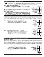
Input Module Component Glossary
LO RANGE
HI RANGE
10%
SPAN Pot %
10%
10%
10%
10%
10%
Signal Span %
20%
30%
40%
50%
1
SPAN Adjust
Header position
Span Adjust Header
Span Adjust Header
Span Range Header
2
3
4
5
10%
10%
10% 10%
10%
60%
70%
80% 90%
100%
1
2
3
4
5
< Decrease Span Increase >
1 2
3
4 5
< Decrease Span Increase >
1 2
3
4 5
Equivalent
Circuit
Acts like a
150 Turn
Potentiometer
Low Range
High Range
Input LO
Input HI
HI
LO
Input and Output Pins
On most modules Pin 1 is the Signal High input
and Pin 3 is the Signal Low input. Typically Pin 2
is used for Excitation Voltage output.
HI
LO
24V
Exc
INPUT RANGE Header
Range values are marked on the PCB. Typically
two to four positions are provided, which are select-
ed with either a single or multiple jumper clip. When
provided, a custom range position is only functional
when the option has been factory installed.
Custom
200V
20V
2V
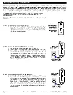
SPAN RANGE Header
When this header is provided it works in conjunc-
tion with the SPAN ADJUST Header by splitting its
adjustment range into a Hi and a Lo range. This
has the effect of dividing the adjustment range of
the SPAN pot into ten equal 10% steps across
100% of the input Signal Span.
Range
HI
LO
HI
LO
SPAN
Turn Clockwise to
Increase Reading
To the
Right Rear
SPAN Potentiometer (Pot)
If provided, the 15 turn SPAN pot is always on the
right side (as viewed from the rear of the meter).
Typical adjustment is 20% of the input signal
range.
< Increase Span Decrease >
5 4
3
2 1
<
Incr
ease
Sp
an D
ecre
ase
>
5 4
3
2 1
20%
SPAN Pot %
20%
20%
20%
20%
20%
Signal Span %
40%
60%
80%
100%
1
SPAN Adjust
Header position
2
3
4
5
< Decrease Span Increase >
12
3
4 5
Acts like 75 Turn 1 Mega Ohm Potentiometer
Input LO
Input
HI
Equivalent
Circuit
SPAN ADJUST Header
This unique five-position header expands the
adjustment range of the SPAN pot into five equal
20% steps, across 100% of the input Signal
Span. Any input Signal Span can then be pre-
cisely scaled down to provide any required Digital
Display span from 1999 counts to 001 (one count).
ZERO
Turn Clockwise to
Increase Reading
To the
Left Rear
15 Turn Potentiometer
⊕
+
100 Counts
⊕
–
100 Counts
–
0
+
ZERO Potentiometer (Pot)
If provided, the ZERO pot is always to the left
of the SPAN pot (as viewed from the rear of the
meter). Typically it enables the input signal to be
offset ±5% of full scale (-100 to +100 counts).


