background image

Mar-14-2016 DI-60 320 DS (NZ301)_UL_March 2016

Page 15

Texmate, Inc. Tel. (760) 598-9899  •  www.texmate.com

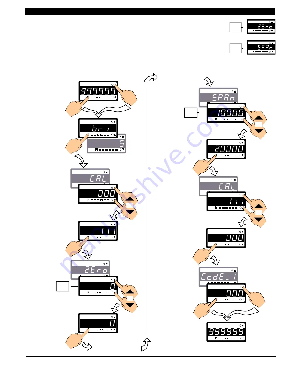
The low input source is applied to 
the meter when setting the zero 
value.
The high input source is applied 
to the meter when setting the 
span value. 

Two-point Calibration

Two-point calibration is the most commonly used method of 
 calibrating Tiger 320 Series meters when a low and high input 
source is available. 

Example Calibration Procedure

Calibrate channel 1 (CH1) using the two-point calibration 
method. The calibration mode display is set to 

[111]

.

[CAL] - Calibration Modes for Input and Output continued

[CAL] - Calibration Modes for Input and Output continued

Prog.

SP1

SP2

SP4

SP3

SP5

SP6

Prog.

SP1

SP2

SP4

SP3

SP5

SP6

Prog.

SP1

SP2

SP4

SP3

SP5

SP6

Prog.

SP1

SP2

SP4

SP3

SP5

SP6

Prog.

SP1

SP2

SP4

SP3

SP5

SP6

Prog.

SP1

SP2

SP4

SP3

SP5

SP6

Prog.

SP1

SP2

SP4

SP3

SP5

SP6

Prog.

SP1

SP2

SP4

SP3

SP5

SP6

Prog.

SP1

SP2

SP4

SP3

SP5

SP6

Prog.

SP1

SP2

SP4

SP3

SP5

SP6

Prog.

SP1

SP2

SP4

SP3

SP5

SP6

Prog.

SP1

SP2

SP4

SP3

SP5

SP6

TEXMATE

Prog.

SP1

SP2

SP4

SP3

SP5

SP6

Prog.

SP1

SP2

SP4

SP3

SP5

SP6

Prog.

SP1

SP2

SP4

SP3

SP5

SP6

Prog.

SP1

SP2

SP4

SP3

SP5

SP6

X

Prog.

SP1

SP2

SP4

SP3

SP5

SP6

Prog.

SP1

SP2

SP4

SP3

SP5

SP6

To Step 7

OR

From Step 6

5.2. Apply the LOW
input signal

OR

OR

Press

1

Press

1

Press

1

Press

1

Press

1

Press

at same

time

Press

at same

time

Press

at same

time

Press

at same

time

Step 1

Step 2

Step 3

Step 4

Step 5

Step 6

7.2. Apply the HIGH
input signal

Step 7

Step 8

Step 9

Step 10

Step 11

Enter Brightness Mode 

Pass Brightness Mode and

enter Calibration Mode

Select Calibration

Mode [111]

Select the No Function
Calibration Mode [000]

Save Calibration Mode [000]

setting and enter Code 1

Operational Display

Operational Display

Exit code 1 and return

to operational display

Enter Cal Mode [111]

For 2-point calibration

of CH1

5.1. Adjust display to
desired reading for
zero input

7.1. Adjust display to
desired reading for
span input

Set reading for zero load into

meter and enter Span Mode

Save zero and span settings
and re-enter Calibration Mode

Example

Example

OR

LOW

Signal

HIGH

Signal

2-POINT CALIBRATION

1st Digit  = 1
Selects calibration procedures
2nd Digit  = 1
Selects 2-point calibration
3rd Digit  = 1
Selects CH1 for calibration

Low

Signal

High

Signal

Prog.

SP1

SP3

SP2

SP4 SP5 SP6

Prog.

SP1

SP3

SP2

SP4 SP5 SP6

Summary of Contents for Tiger 320 DI-60E

Page 1: ...tage or optional low voltage AC DC power supply Serial output options include RS 232 RS 485 ModBus Ethernet or direct meter to meter communications Single or dual 16 bit Isolated Analog Outputs Progra...

Page 2: ...r smart setpoints with fully configurable hysteresis on and off delays one shot pulse and repeat timers latching dual PID set point tracking resetting of registers initiating of logging and printing S...

Page 3: ...ard 1 Single Analog Output Fully scalable from 4 to 20mA or 0 to 20mA or reverse and selectable for 0 to 10VDC or reverse 2 Dual Analog Output Fully scalable from 0 to 10VDC or reverse Outputs continu...

Page 4: ...VERSE OF INPUT LINEARIZATION LOG OF INPUT Bargraph display only RTD SAMPLE RATE SMART AUTO ZERO SQUARE ROOT THERMOCOUPLES DECIMALS RIGHT HAND CHARACTER AND ROUNDING FOR CH1 2 3 4 RESULT AND DEFAULT DI...

Page 5: ...Mar 14 2016 DI 60 320 DS NZ301 _UL_March 2016 Page 5 Texmate Inc Tel 760 598 9899 www texmate com THIS PAGE INTENTIONALLY LEFT BLANK...

Page 6: ...perational display pressing the button initiates a viewing mode that allows you to view the readings on chan nels 2 and 4 setpoints 2 4 and 6 valley and total 2 Once into the viewing routine pressing...

Page 7: ...nnel 2 XX2 Reset channel 3 XX3 Reset channel 4 XX4 Reset tare XX5 Reset total 1 XX6 Unlatch de energize all setpoints XX7 Hold Pin Configure Code 9 to X0X When the HOLD pin pin 9 is con nected to the...

Page 8: ...00 is shown If an X appears in place of a digit this means that any number displayed in that digit is not relevant to the function being explained Where a left and right hand are shown on separate but...

Page 9: ...e digit configuration settings that are applied individually to each set point See Page 33 for an exam ple procedure to configure a setpoint for simple relay functions Front Panel Programming Codes Th...

Page 10: ...anual loader manual offset Print View Mode Ch3 SP_1 SP_3 SP_5 PEAK tot_1 Ch1 Operational Display To view press the button View Mode Ch4 SP_2 SP_4 SP_6 VALEY tot_2 Ch2 To view press the button Operatio...

Page 11: ...ogram or the Meter Configuration program Turning the macro OFF means that the meter will not perform the automatic commands pre programmed to run with the macro Unless requested to blank out all or so...

Page 12: ...ngs by entering the main programming mode Initial Setup Procedures bri Display Brightness Initial Setup Procedures Initial Setup Procedures continued Programming Tip Code Blanking and Macro ON OFF set...

Page 13: ...RTD 385 input source 4 Calibrate Smart Input Module Note This function is not available on all input modules 5 Calibrate Analog Output mA V requires multimeter connected to pins 16 and 17 6 7 0 Set b...

Page 14: ...to 255 samples The averaging win dow can be set to between 1 and 65535 counts See the calibration modes diagram on Page 13 showing a breakdown of 1st 2nd and 3rd digits See Input Signal Sampling Show...

Page 15: ...SP2 SP4 SP3 SP5 SP6 Prog SP1 SP2 SP4 SP3 SP5 SP6 Prog SP1 SP2 SP4 SP3 SP5 SP6 X Prog SP1 SP2 SP4 SP3 SP5 SP6 Prog SP1 SP2 SP4 SP3 SP5 SP6 To Step 7 OR From Step 6 5 2 Apply the LOW input signal OR OR...

Page 16: ...SP6 Prog SP1 SP2 SP4 SP3 SP5 SP6 Prog SP1 SP2 SP4 SP3 SP5 SP6 Prog SP1 SP2 SP4 SP3 SP5 SP6 Prog SP1 SP2 SP4 SP3 SP5 SP6 Prog SP1 SP2 SP4 SP3 SP5 SP6 TEXMATE Prog SP1 SP2 SP4 SP3 SP5 SP6 Prog SP1 SP2 S...

Page 17: ...the Display Format sub menu Selecting X7X enters the Last Digit Text Character sub menu Data Source Second Digit X5X The data source for the primary display is configured by selecting 5 in the second...

Page 18: ...ns are only for use with meters that have more than one display With bar graph meters the PRIMARY display is the digital display and the SECONDARY display is the bargraph display LAST DIGIT ROUNDING 0...

Page 19: ...Note Options 1 and 2 listed for the 3rd digit in Step 3 above are only for use with meters that have more than one display With bargraph meters the PRIMARY display is the digital display and the SECON...

Page 20: ...isplay digits 4 and 5 by setting Code 1 to X61 Initial Setup Procedures CodE_1 Display Configuration continued Prog SP1 SP2 SP4 SP3 SP5 SP6 Prog SP1 SP2 SP4 SP3 SP5 SP6 Prog SP1 SP2 SP4 SP3 SP5 SP6 Pr...

Page 21: ...SP2 SP4 SP3 SP5 SP6 Prog SP1 SP2 SP4 SP3 SP5 SP6 Prog SP1 SP2 SP4 SP3 SP5 SP6 Prog SP1 SP2 SP4 SP3 SP5 SP6 Step 1 Step 2 Step 3 Operational Display Operational Display Example Press 2 Press at same ti...

Page 22: ...SP3 SP5 SP6 Prog SP1 SP2 SP4 SP3 SP5 SP6 Prog SP1 SP2 SP4 SP3 SP5 SP6 Prog SP1 SP2 SP4 SP3 SP5 SP6 Prog SP1 SP2 SP4 SP3 SP5 SP6 Step 1 Step 2 Step 3 Operational Display Operational Display Example Pr...

Page 23: ...ter 6 6 Output Register 7 7 Smart Input Module Setup THIRD DIGIT FIRST DIGIT SECOND DIGIT 0 Sample Rate Typically 10 samples second 60 Hz rejection Output Rate 0 1 seconds See Example 1 Sample Rate Ty...

Page 24: ...See Note 5 4 32 point Linearization on CH1 using Table 4 See Note 5 5 125 point Linearization on CH1 Tables 1 to 4 cascaded See Note 5 6 32 point Linearization on CH1 Tables 1 to 4 selected from the r...

Page 25: ...AL INPUT 0 Frequency 99 999 Hz range from 0 01 Hz 1 Frequency 999 99 Hz range from 0 01 Hz 2 Frequency 99 999 kHz range from 1 Hz 1 s gate 3 Frequency 500 kHz range from 10 Hz 0 1 s gate 4 Period 9 99...

Page 26: ...gister CODE 5 CHANNEL 3 FUNCTIONS FIRST DIGIT SECOND DIGIT THIRD DIGIT CH3 POST PROCESSING FOR REAL TIME CLOCK TIMER 0 HRS MIN SEC 1 HRS MIN 2 3 4 1 Second Count UP Timer 5 1 Second Count DOWN Timer 6...

Page 27: ...put Modules Guide Z87 for code details Code 6 is a single code that combines all the configuration and post processing functions available for Channel 4 When a quad input signal con ditioner is instal...

Page 28: ...oint program mable linearization table available For four 32 point programmable linearization tables to be available the meter requires at least 32 kB of memory to be installed Meters with 4 kB Memory...

Page 29: ...t 3 Hrs Min Sec with CR LF 4 Spreadsheet Format No time stamp with print log 5 Spreadsheet Format Time stamp format 1 Mth Day Yr Hrs Min Sec 6 Spreadsheet Format Time stamp format 2 Day Mth Yr Hrs Min...

Page 30: ...utput modules support a combination of 4 5 A Form A and 9 10 A Form C relays providing 12 configuration options A solid state relay SSR output module supports 300 V 210 mA DC SSRs A 22 opto isolated I...

Page 31: ...t flashing until the setpoint de activates Setpoint Tracking Setpoint tracking can be applied to setpoints configured in the hyster esis deviation or PID modes tions PID control is available from the...

Page 32: ...de for users who require the following basic setpoint and relay functions First Digit Relay Energize Functions Relays programmed to energize above or below the setpoint value Second Digit SP Activatio...

Page 33: ...og SP1 SP2 SP4 SP3 SP5 SP6 Prog SP1 SP2 SP4 SP3 SP5 SP6 Prog SP1 SP2 SP4 SP3 SP5 SP6 Prog SP1 SP2 SP4 SP3 SP5 SP6 Prog SP1 SP2 SP4 SP3 SP5 SP6 Prog SP1 SP2 SP4 SP3 SP5 SP6 Prog SP1 SP2 SP4 SP3 SP5 SP6...

Page 34: ...ut D2 5 Digital Input D3 6 HOLD Pin 7 LOCK Pin SP Delay Timing Functions FIRST DIGIT SECOND DIGIT THIRD DIGIT See Set Up H y s t e r e s i s Deviation PID Mode Settings below Go to Page 35 The diagram...

Page 35: ...0 0 0 001 to 6553 5 65 535 secs Minimum off time M_of 0 0 to 6553 5 secs X X X X Reset SPC_ X to XX0 P Programming Tip If you do not require any of the functions in this mode ensure it is set to Progr...

Page 36: ...t hold the button down while cycling through the decades and release it when oFF or tArE appears Registers that Should Not be Used The following registers are contained within the selectable 1 to 244...

Page 37: ...rt Modules incorporate their own A D converters and communicate digitally with the meter See section on I Series Input Modules for connection details 17 Bit Dual Slope A D Converter VREF Cref Comp A B...

Page 38: ...9A 9A SP3 SP1 SP4 SP2 Relay Modules with up to two 4 5A Form A Relays and up to two 9 10A Form C Relays 32 31 30 28 29 27 26 25 Options Order Code OR51 OR52 OR53 OR54 210mA 210mA 210mA 210mA 210mA 21...

Page 39: ...ocess control applications Modular construction ensures you don t have to pay for unnecessary hardware Simply order the input and output options to suit your application Input Signal Conditioning Modu...

Page 40: ...PCB Shown with optional Input Signal Conditioning Module Ordered Separately Hi Volt Order Code PS1 Lo Volt Order Code PS2 ID01 10 Digital Outputs Add on Board Standard 6 Digital Inputs 6 Digital Outpu...

Page 41: ...oisy components Shielding cables for input output leads is recommended with shield connection to earth ground near the meter preferred 4 A circuit breaker or disconnect switch is required to disconnec...

Page 42: ...Code 3 Channel 1 Post Processing and Serial Mode Functions 24 Code 4 Channel 2 Measurement Task and Sampling Rate 25 Code 5 Channel 3 Functions 26 Code 6 Channel 4 Functions 27 Code 7 Result Processi...

Page 43: ...d Not Be Selected 36 Resetting and Incrementing Using Setpoints 36 Relay Logic Output Modules 38 Serial Communication Configuration 24 Pinouts 38 Setpoint Programming Mode 30 35 Data Logging 31 Data P...

Page 44: ...mate com Texmate has facilities in Japan Taiwan and Thailand Case Dimensions Copyright 2004 2016 Texmate Inc All Rights Reserved Clear Lockable NEMA 4X Splash Proof Cover P N OP N4 96x48 The 96x48mm c...

Reviews: