Mar-14-2016 DI-60 320 DS (NZ301)_UL_March 2016
Page 23
Texmate, Inc. Tel. (760) 598-9899 • www.texmate.com
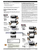
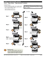
Example Procedure:
Configure CH1 for a voltage input with 10 samples/second
(60 Hz rejection) sampling rate and output rate of 0.1 secs by
setting Code 2 to [
000
].
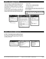
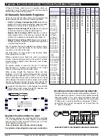
The Tiger 320 Series DI-60 meter can be configured to measure
almost any input signal. The measurement task and sampling rate
for Channel 1 (CH1) is configured in the three digits of Code 2. The
diagram below lists the available configuration selections in Code 2.
FOR VOLTAGE
0 No function
1 Peak detector
2 Pressure with Auto-cal
FOR THERMOCOUPLE
0 Type J
1 Type K
2 Type R
3 Type S
4 Type T
5 Type B
6 Type N
7 Select User Defined Table 1 set-up in
Code 3 [X7X]. To invoke Table 1, reset
Code 3 to [00X]
FOR RTD TYPE (2-, 3-, 4- WIRE)
0 Resistance
1 RTD 385
2 RTD 392
3 RTD 120
4 Cn 10
FREQUENCY RANGE
0 99.999 Hz range from 0.010 Hz
1 99.999 Hz range from 2.000 Hz
2 999.99 Hz range from 0.01 Hz
3 999.99 Hz range from 2.00 Hz
4 9999.9 Hz range from 0.1 Hz
5 9999.9 kHz range from 2.0 Hz
6 99 kHz range from 1 Hz (1 s gate)
7 655.35 kHz range from 10 Hz (0.1 s gate)
PERIOD MEASUREMENT
0 99.999 s
1 9.9999 s
2 999.99 ms
3 99.999 ms
COUNTER/RESIDENT TIMER/CLOCK
0 Counter input with 16 bit Pre-scaler
1 Setting of 16-bit Pre-scaler
2 Pre-scaler and Debounced counter
3 Up/Down Counter with Pre-scaler
4 Stop watch HRS:MIN:SEC
5 Stop watch DAYS:HRS:MIN
6 External 24-hour clock
7 Internal 24-hour clock
ANALOG SAMPLE RATE
MEASUREMENT TASK
0 Voltage, Current
1 TC (third digit selects type of TC)
2 RTD 3-wire (third digit selects type of RTD)
3 RTD 2- or 4-wire (third digit selects type of RTD)
4 Frequency
5 Period
6 Counter
7 Smart Input Module
CODE 2 – CHANNEL 1 MEASUREMENT TASK AND SAMPLING RATE
SMART INPUT MODULE
0 Output Register 1
1 Output Register 2
2 Output Register 3
3 Output Register 4
4 Output Register 5
5 Output Register 6
6 Output Register 7
7 Smart Input Module Setup.
THIRD DIGIT
FIRST DIGIT
SECOND DIGIT
0 Sample Rate: Typically 10 samples/second (60 Hz rejection)
Output Rate: 0.1 seconds
See Example
1 Sample Rate: Typically 10 samples/second (50 Hz rejection)
Output Rate: 0.1 seconds
See Example
2 Sample Rate: Typically 10 samples/second (60 Hz rejection)
Output Rate: 10 millisecs
See Example
3 Sample Rate: Typically 10 samples/second (50 Hz rejection)
Output Rate: 10 millisecs
See Example
Note:
Output Rate refers to setpoint and macro outputs, and input
rates from smart input modules.
Note:
All above sample rates are quoted for single channel operation.
Where more than one channel is available, sample rates are
divided by the number of active channels. See Example.
1 Channel = 10 samples/second
2 Channels = 5 samples/second
3 Channels = 3.33 samples/second
4 Channels = 2.5 samples/second
Example: 10 Samples/Second
Initial Setup Procedures
[CodE_2] - Channel 1 Measurement Task & Sampling Rate
1 =
0.1 second
10 =
1 second
600 =
1 minute
36000 = 1 Hour***
X61 Sets Prescaler
Use
buttons to set
prescale values
***Note: For the 1 hour
setting, the scale factor
for CH1 must be set to
0.1 in the calibration
mode setting [111].
P
Press
Use the
buttons to set the
required smart input module code
(0 to 377). See
I-Series Input
Module Guide (Z87)
for code
details.
Prog.
SP1
SP2
SP4
SP3
SP5
SP6
Prog.
SP1
SP2
SP4
SP3
SP5
SP6
Press
1
Prog.
SP1
SP2
SP4
SP3
SP5
SP6
Prog.
SP1
SP2
SP4
SP3
SP5
SP6
Prog.
SP1
SP2
SP4
SP3
SP5
SP6
Prog.
SP1
SP2
SP4
SP3
SP5
SP6
Prog.
SP1
SP2
SP4
SP3
SP5
SP6
Prog.
SP1
SP2
SP4
SP3
SP5
SP6
Prog.
SP1
SP2
SP4
SP3
SP5
SP6
Step 1
Step 2
Step 3
Operational Display
Operational Display
Press
3
Press
at same
time
Press
at same
time
OR
Step 4
Press
at same
time
Press
at same
time
Step 5
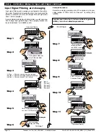
CONFIGURING CH1 MEASUREMENT TASK & SAMPLING
RATE PROCEDURE
Pass Brightness Mode,
Calibration Mode, Code 1,
and enter Code 2
To Step 5
Enter Brightness Mode
Save setting and
enter Code 3
Exit Code 3. Return to
Operational Display
1st Digit = 0 Selects 10 samples/sec (60 Hz)
2nd Digit = 0 Selects voltage, current
3rd Digit = 0 Selects no function


