7
2 February, 2005 Code Sheet V4.01d (NZ1001)
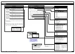
0 Functions Activated
by Pressing the
PROGRAM Button
1 Calibration
Procedures
2 Related Calibration
Functions
3 -
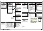
CALIBRATION MODES FOR INPUT AND OUTPUT
FIRST DIGIT
SECOND DIGIT
0 Serial Communications
Properties
1 Set Auto Zero Maintenance
for 3rd digit
2 Set Averaging Samples &
Averaging Window for 3rd
digit
3 Totalizer Settings Mode
4 Setup 32-point
Linearization Tables
5 Scale Analog Output
LOW/HIGH Scale Range
Settings
6 -
7 -
See Page 6 for a break-
down of the sub-menu
See Page 6 for a break-
down of the sub-menu
OBJECT FOR 2nd DIGIT
THIRD DIGIT
Auto zero capture band
Use
buttons to set
AZ_APT from
0 to 65535
counts
Auto zero motion
Auto zero aperture window
Use
buttons to set
AZ_CAP from 1 to 254 counts
Use buttons
to
set averag-
ing samples from 0 to 255 counts
Use
buttons to set averaging
window from 0 to 65535 counts
Rate-of-change in counts per second
Use buttons
to
set LOW display reading
[CAL_L]
Use
buttons to set
HIGH display reading [CAL_h]
Select the method of configuring the user defined
linearization table:
manual
or
auto
setup mode.
Then set the table number, date, and serial number
before setting the linearization points. Or select [init]
to re-initialize the default table settings.
Note:
The input channel setting in
the 3rd digit is
not
relevant to
the
manual setup mode
.
Note:
The correct input signal channel must be
selected in the 3rd digit when configuring a lin-
earization table using the
auto setup mode
.
0
-
1
CH1
2
CH2
3
CH3
4
CH4
5
CH5
6
CH6
7
CH7
THIRD DIGIT
THIRD DIGIT
THIRD DIGIT
Use
buttons to set
AZ_MOT from
0 to 255 counts
Use
buttons to set time period
Use
buttons to set
total from 1 to
65535
Default setting 10,000 counts
Use
buttons to set
Cutoff from –19999 to 32767
Use buttons
to
set rollover to ON or OFF
Use
buttons to set input rate
Use
buttons to select mode
Use
buttons to set parity
Use
buttons to select baud rate
Use
buttons to set address
Modbus RTU protocol
Macro controlled serial output
Print directly to serial printer or PC
Ethernet
DeviceNet
Touchpanel
Modbus master
Up to 255
Select the settings for the seri-
al port selected in the 3rd digit
THIRD DIGIT
Use
buttons to select source for totalizer
Use
buttons to select source for analog output
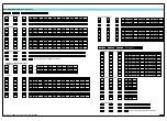
For data source selection options, see
Select Data Source
diagram on Page 8
For data source selection options, see
Select Data Source
diagram on Page 8
0
Result
1
Channel 1
2
Channel 2
3
Channel 3
4
Channel 4
5
Channel 5
6
Channel 6
7
Channel 7
THIRD DIGIT
0
-
1
Port 1
2
Port 2
3
Port 3
Note: Port 3 only
available on certain
input modules
These settings show the full
range of the baud rate.
The available baud rate differs
for ports 1 to 3.
0
-
1
Total 1
2
Total 2
3
Total 3
4
Total 4
5
Total 5
6
Total 6
0
-
1
Analog Output 1
2
Analog Output 2
3
Analog Output 3
4
Analog Output 4
5
Analog Output 5
6
Analog Output 6
7
Analog Output 7
Note: Settings 3-7
not available at
present


