5
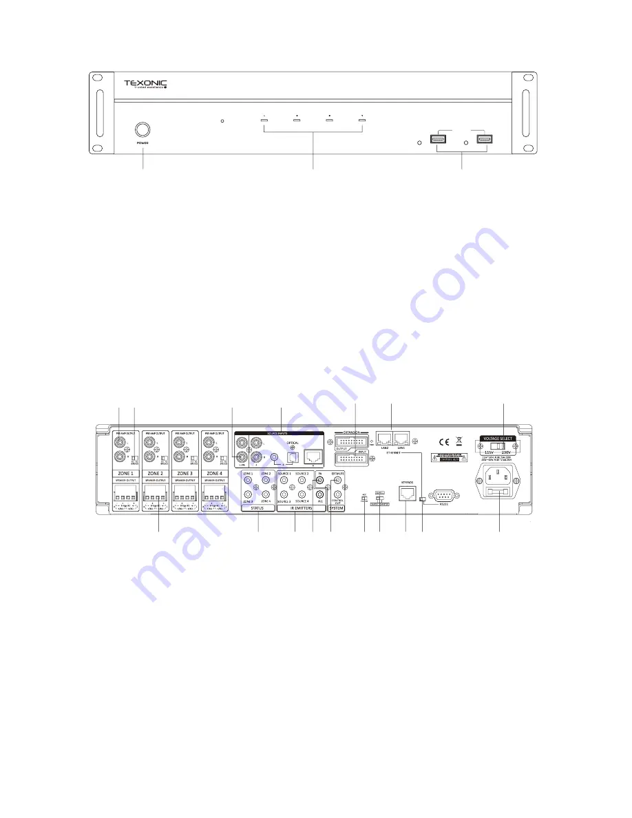
1. Power ON/OFF/ STANDBY
Depress the power button to turn
on the system. Press it again to
release the latch and power the
unit off. Note that even the Master
Controller is powered on, each
zone will remain in Standby mode
until the zone keypad is activated.
SOURCE INPUTS
4
5
LINK
LINK
RX800
13 14
17
2
6
7 8
9
15
1 3
5
4
10
12
11
16
REAR PANEL
1. PRE-AMP OUTPUT
Stereo Line level output on each zone.
Connect to additional amplifier with higher
output, or powered Sub-woofers.
2.SPEAKER OUTPUTS
Removable terminal block connectors on
each zone.
Each zone provides 2x50W @ 4 Ohm or
100W @ 8 Ohm in bridge mode.
3.STEREO/BRIDGE SWITCH
4.SOURCE INPUTS
6 Stereo Analog/Digital inputs.
Two Streamers are input 4 and 5.
5.Input 1/PA
Paging capability for Input 1 to broadcast to all
zones when 12VDC is applied to the PA - IN jack.
6.STATUS
When the zone is activated, the corresponding
jack will output 12VDC to trigger other device.
7.IR EMITTERS
IR Outputs 4 routed & 1 common
8.PA-IN
12VDC paging trigger input
9.EXT. MUTE/CONTROL OUT
Mute the entire system with the 12VDC MUTE IN.
Use the12VDC CONTROL OUT to trigger other
equipment
2. Standby/Zone ON LED
These four LEDs illuminate to indicate the
status of each zone.
Blue: In Standby mode.
White: In Activate mode.
Blue/White: In Mute mode.
3. USB Port 4/5
Two USB ports correspond to the built-in
Streamers, as source input 4 and 5. Playing
audio source from USB Flash Drives.
1
2
3
FRONT PANEL
Summary of Contents for RX 800
Page 2: ...2 ...
Page 7: ...7 1 7 2 5 6 3 4 3 ...
Page 8: ...8 RX 800 RX 800 RCA 3 5mm Stereo ...
Page 12: ...12 four 4 ...


