background image

SECTION 7

CESSNA

AIRPLANE AND SYSTEM DESCRIPTION

MODEL 172S NAV III

KAP 140 AUTOPILOT

U.S.

ELECTRICAL SYSTEM


(Continued)

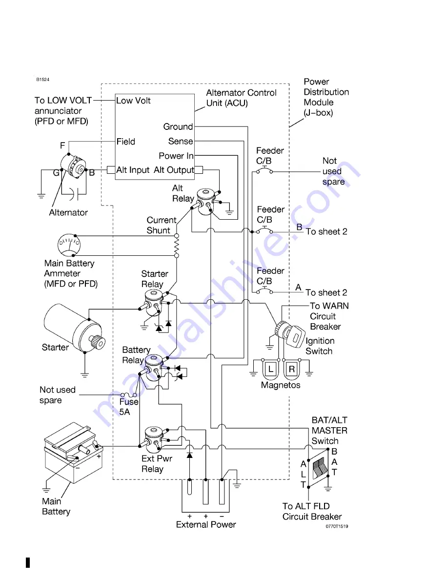
Figure 7-7 (Sheet 1 of 3)*

172SPHAUS-05

7-48

For 

Training 

Purposes 

Only

Summary of Contents for Cessna 172S NAV III Skyhawk SP

Page 1: ...nformation Manual 172S NAV III Skyhawk SP MODEL 172S NAV III AVIONICS OPTION KAP 140 AUTOPILOT Serials 172S9810 thru 172S10467 and 172S10469 thru 172S10506 and 172S10508 thru 172S10639 and 172S10641 t...

Page 2: ...F o r T r a i n i n g P u r p o s e s O n l y...

Page 3: ...URPOSES ONLY IT WILL NOT BE KEPT CURRENT AND THEREFORE CANNOT BE USED AS A SUBSTITUTE FOR THE OFFICIAL PILOT S OPERATING HANDBOOK AND FAA APPROVED AIRPLANE FLIGHT MANUAL INTENDED FOR OPERATION OF THE...

Page 4: ...RS Range 45 Power at 10 000 Feet Range 638 NM 53 Gallons Usable Fuel Time 6 72 HOURS RATE OF CLIMB AT SEA LEVEL 730 FPM SERVICE CEILING 14 000 FEET TAKEOFF PERFORMANCE Ground Roll 960 FEET Total Dista...

Page 5: ...uipped with speed fairings which increase the speeds by approximately 2 knots There is a corresponding difference in range while all other performance figures are unchanged when speed fairings are ins...

Page 6: ...F o r T r a i n i n g P u r p o s e s O n l y...

Page 7: ...nd 172S10469 thru 172S10506 and 172S10508 thru 172S10639 and 172S10641 thru 172S10655 THIS MANUAL INCORPORATES INFORMATION ISSUED IN THE PILOT S OPERATING HANDBOOK AND FAA APPROVED AIRPLANE FLIGHT MAN...

Page 8: ...F o r T r a i n i n g P u r p o s e s O n l y...

Page 9: ...S SECTION GENERAL 1 LIMITATIONS 2 EMERGENCY PROCEDURES 3 NORMAL PROCEDURES 4 PERFORMANCE 5 WEIGHT AND BALANCE EQUIPMENT LIST 6 AIRPLANE AND SYSTEMS DESCRIPTION 7 HANDLING SERVICE AND MAINTENANCE 8 SUP...

Page 10: ...F o r T r a i n i n g P u r p o s e s O n l y...

Page 11: ...Entry Dimensions 1 9 Baggage Space And Entry Dimensions 1 9 Specific Loadings 1 9 Symbols Abbreviations And Terminology 1 10 General Airspeed Terminology And Symbols 1 10 Meteorological Terminology 1...

Page 12: ...F o r T r a i n i n g P u r p o s e s O n l y...

Page 13: ...CESSNA SECTION 1 MODEL 172S NAV III GENERAL KAP 140 AUTOPILOT U S THREE VIEW NORMAL GROUND ATTITUDE Figure 1 1 Sheet 1 of 2 1 3 172SPHAUS 05 F o r T r a i n i n g P u r p o s e s O n l y...

Page 14: ...ase length is 65 0 inches Propeller ground clearance is 11 25 inches Wing area is 174 0 square feet Minimum turning radius pivot point to outboard wing tip is 27 0 feet 5 50 inches Normal ground attit...

Page 15: ...terminology commonly used DESCRIPTIVE DATA ENGINE Number of Engines 1 Engine Manufacturer Textron Lycoming Engine Model Number IO 360 L2A Engine Type Normally aspirated direct drive air cooled horizon...

Page 16: ...concentrations shall not exceed 1 for isopropyl alcohol or 0 10 to 0 15 for DiEGME Refer to Section 8 for additional information FUEL CAPACITY Total Capacity 56 0 U S GALLONS Total Usable 53 0 U S GA...

Page 17: ...de Ashless Dispersant Oil Oil conforming to Textron Lycoming Service Instruction No 1014 and all revisions and supplements thereto must be used after first 50 hours or oil consumption has stabilized R...

Page 18: ...Category 2200 POUNDS WEIGHT IN BAGGAGE COMPARTMENT NORMAL CATEGORY Baggage Area A Station 82 to 108 120 POUNDS Refer to note below Baggage Area B Station 108 to 142 50 POUNDS Refer to note below NOTE...

Page 19: ...ad Utility Category 545 POUNDS CABIN AND ENTRY DIMENSIONS Detailed dimensions of the cabin interior and entry door openings are illustrated in Section 6 BAGGAGE SPACE AND ENTRY DIMENSIONS Dimensions o...

Page 20: ...FE Maximum Flap Extended Speed is the highest speed permissible with wing flaps in a prescribed extended position VNO Maximum Structural Cruising Speed is the speed that should not be exceeded except...

Page 21: ...arometric scale has been set to 29 92 inches of mercury 1013 mb ENGINE POWER TERMINOLOGY BHP Brake Horsepower is the power developed by the engine RPM Revolutions Per Minute is engine speed Static RPM...

Page 22: ...e to provide a greater portion of fuel is known as richening the mixture Full Rich Mixture control full forward pushed in full control travel toward the panel Idle Cutoff Mixture control full aft pull...

Page 23: ...Fuel Usable Fuel is the fuel available for flight planning Unusable Fuel Unusable Fuel is the quantity of fuel that can not be safely used in flight GPH Gallons Per Hour is the amount of fuel consume...

Page 24: ...in this POH to simplify balance calculations by reducing the number of digits Center of Gravity C G Center of Gravity is the point at which an airplane or equipment would balance if suspended Its dis...

Page 25: ...flight range as that of the actual wing Maximum Ramp Weight Maximum Ramp Weight is the maximum weight approved for ground maneuver and includes the weight of fuel used for start taxi and runup Maximu...

Page 26: ...easurement supplied with the Pilot s Operating Handbook into metric and imperial measurements The standard followed for measurement units shown is the National Institute of Standards Technology NIST P...

Page 27: ...CESSNA SECTION 1 MODEL 172S NAV III GENERAL KAP 140 AUTOPILOT U S WEIGHT CONVERSIONS Figure 1 2 Sheet 1 of 2 1 17 172SPHAUS 05 F o r T r a i n i n g P u r p o s e s O n l y...

Page 28: ...SECTION 1 CESSNA GENERAL MODEL 172S NAV III KAP 140 AUTOPILOT U S WEIGHT CONVERSIONS Figure 1 2 Sheet 2 172SPHAUS 05 1 18 F o r T r a i n i n g P u r p o s e s O n l y...

Page 29: ...CESSNA SECTION 1 MODEL 172S NAV III GENERAL KAP 140 AUTOPILOT U S LENGTH CONVERSIONS Figure 1 3 Sheet 1 of 4 1 19 172SPHAUS 05 F o r T r a i n i n g P u r p o s e s O n l y...

Page 30: ...SECTION 1 CESSNA GENERAL MODEL 172S NAV III KAP 140 AUTOPILOT U S LENGTH CONVERSIONS Figure 1 3 Sheet 2 172SPHAUS 05 1 20 F o r T r a i n i n g P u r p o s e s O n l y...

Page 31: ...CESSNA SECTION 1 MODEL 172S NAV III GENERAL KAP 140 AUTOPILOT U S LENGTH CONVERSIONS Figure 1 3 Sheet 3 1 21 172SPHAUS 05 F o r T r a i n i n g P u r p o s e s O n l y...

Page 32: ...SECTION 1 CESSNA GENERAL MODEL 172S NAV III KAP 140 AUTOPILOT U S LENGTH CONVERSIONS Figure 1 3 Sheet 4 172SPHAUS 05 1 22 F o r T r a i n i n g P u r p o s e s O n l y...

Page 33: ...CESSNA SECTION 1 MODEL 172S NAV III GENERAL KAP 140 AUTOPILOT U S DISTANCE CONVERSIONS Figure 1 4 1 23 172SPHAUS 05 F o r T r a i n i n g P u r p o s e s O n l y...

Page 34: ...SECTION 1 CESSNA GENERAL MODEL 172S NAV III KAP 140 AUTOPILOT U S VOLUME CONVERSIONS Figure 1 5 Sheet 1 of 3 1 24 172SPHAUS 05 F o r T r a i n i n g P u r p o s e s O n l y...

Page 35: ...CESSNA SECTION 1 MODEL 172S NAV III GENERAL KAP 140 AUTOPILOT U S VOLUME CONVERSIONS Figure 1 5 Sheet 2 1 25 172SPHAUS 05 F o r T r a i n i n g P u r p o s e s O n l y...

Page 36: ...SECTION 1 CESSNA GENERAL MODEL 172S NAV III KAP 140 AUTOPILOT U S VOLUME CONVERSIONS Figure 1 5 Sheet 3 1 26 172SPHAUS 05 F o r T r a i n i n g P u r p o s e s O n l y...

Page 37: ...CESSNA SECTION 1 MODEL 172S NAV III GENERAL KAP 140 AUTOPILOT U S TEMPERATURE CONVERSIONS Figure 1 6 1 27 172SPHAUS 05 F o r T r a i n i n g P u r p o s e s O n l y...

Page 38: ...SECTION 1 CESSNA GENERAL MODEL 172S NAV III KAP 140 AUTOPILOT U S PRESSURE CONVERSION HECTOPASCALS TO INCHES OF MERCURY Figure 1 7 172SPHAUS 05 1 28 F o r T r a i n i n g P u r p o s e s O n l y...

Page 39: ...CESSNA SECTION 1 MODEL 172S NAV III GENERAL KAP 140 AUTOPILOT U S VOLUME TO WEIGHT CONVERSION Figure 1 8 172SPHAUS 05 1 29 F o r T r a i n i n g P u r p o s e s O n l y...

Page 40: ...SECTION 1 CESSNA GENERAL MODEL 172S NAV III KAP 140 AUTOPILOT U S QUICK CONVERSIONS Figure 1 9 172SPHAUS 05 1 30 F o r T r a i n i n g P u r p o s e s O n l y...

Page 41: ...ategory 2 8 Center Of Gravity Limits 2 9 Normal Category 2 9 Utility Category 2 9 Maneuver Limits 2 10 Normal Category 2 10 Utility Category 2 10 Flight Load Factor Limits 2 11 Normal Category 2 11 Ut...

Page 42: ...F o r T r a i n i n g P u r p o s e s O n l y...

Page 43: ...ection 9 of this Pilot s Operating Handbook for amended operating limitations operating procedures performance data and other necessary information for airplanes equipped with specific options The air...

Page 44: ...xceed Speed 160 163 Do not exceed this speed in any operation VNO Maximum Structural Cruising Speed 126 129 Do not exceed this speed except in smooth air and then only with caution VA Maneuvering Spee...

Page 45: ...p Operating Range Lower limit is maximum weight VSO in landing configuration Upper limit is maximum speed permissible with flaps extended Green Arc 48 129 Normal Operating Range Lower limit is maximum...

Page 46: ...WITH INDICATED OIL PRESSURE BELOW THE GREEN BAND RANGE WHILE IN CRUISE OR CLIMB CONFIGURATION IS CONSIDERED ABNORMAL REFER TO SECTION 3 AMPLIFIED EMERGENCY PROCEDURES LOW OIL PRESSURE Fuel Grade Refer...

Page 47: ...LINE MIN RED ARC LWR YELLOW ARC GREEN ARC NORMAL OPERATING RANGE RED ARC UPR Tachometer Sea Level 5000 Feet 10 000 Feet 2100 to 2500 2100 to 2600 2100 to 2700 RPM 2700 to 3000 RPM Cylinder Head Temper...

Page 48: ...o 108 120 POUNDS Refer to note below Baggage Area B Station 108 to 142 50 POUNDS Refer to note below NOTE The maximum allowable combined weight capacity for baggage in areas A and B is 120 pounds UTIL...

Page 49: ...ft of datum at 2550 pounds Aft 47 3 inches aft of datum at all weights Reference Datum Lower portion of front face of firewall UTILITY CATEGORY Center of Gravity Range Forward 35 0 inches aft of datum...

Page 50: ...ation Abrupt use of the controls is prohibited above 105 KNOTS UTILITY CATEGORY This airplane is not designed for purely aerobatic flight However in the acquisition of various certificates such as com...

Page 51: ...ose down Proper speed control is an essential requirement for execution of any maneuver and care should always be exercised to avoid excessive speed which in turn can impose excessive loads In the exe...

Page 52: ...ht into known icing conditions is prohibited The minimum equipment for approved operations required under the Operating Rules are defined by 14 CFR 91 and 14 CFR 135 as applicable The following Kinds...

Page 53: ...TION COMMENTS V F R D A Y V F R N I G H T I F R D A Y I F R N I G H T PLACARDS AND MARKINGS 1 172S Nav III KAP 140 Autopilot POH AFM 1 1 1 1 Accessible to pilot in flight 2 Bendix King KAP 140 2 Axis...

Page 54: ...t Occupants FLIGHT CONTROLS 1 Flap Position Indicator 1 1 1 1 2 Flap Motor 1 1 1 1 3 Elevator Trim System 1 1 1 1 4 Elevator Trim Indicator 1 1 1 1 FUEL SYSTEM 1 Electric Fuel Pump 1 1 1 1 2 Fuel Quan...

Page 55: ...D A Y V F R N I G H T I F R D A Y I F R N I G H T LIGHTING 1 PFD Bezel Lighting 0 0 0 1 2 PFD Backlighting 1 1 1 Refer to Note 2 3 MFD Bezel Lighting 0 0 0 1 4 MFD Backlighting 1 1 1 Refer to Note 3...

Page 56: ...meter 0 0 1 1 5 G1000 Vertical Speed Indicator 0 0 0 0 6 G1000 Attitude Indicator 0 0 1 1 7 Standby Attitude Indicator 0 0 1 1 8 G1000 Directional Indicator HSI 0 0 1 1 9 G1000 Turn Coordinator 0 0 1...

Page 57: ...G H T I F R D A Y I F R N I G H T VACUUM 1 Engine Driven Vacuum Pump 0 0 1 1 2 Vacuum Indicator 0 0 1 1 ENGINE FUEL AND CONTROL 1 Fuel Flow Indicator 1 1 1 1 ENGINE INDICATING 1 Tachometer RPM 1 1 1 1...

Page 58: ...1 for normal ground attitude definition Takeoff and land with the fuel selector valve handle in the BOTH position Maximum slip or skid duration with one tank dry 30 seconds Operation on either LEFT o...

Page 59: ...portable electronic device s will not cause interference with the navigation or communication system of the airplane 12V POWER SYSTEM The 12 Volt Power System POWER OUTLET 12V 10A is not certified fo...

Page 60: ...of the pilot to see and maneuver to avoid traffic Use of the TERRAIN PROXIMITY information for primary terrain avoidance is prohibited The Terrain Proximity map is intended only to enhance situationa...

Page 61: ...d instrument approach procedure other than GPS or RNAV that is anticipated to be operational and available at the estimated time of arrival All equipment required for this procedure must be installed...

Page 62: ...extent necessary to comply with TAWS B warnings The geographic area of the TAWS B database must match the geographic area in which the airplane is being operated Serials 172S9810 thru 172S10467 and 1...

Page 63: ...ollowing information must be displayed in the form of composite or individual placards 1 In full view of the pilot The DAY NIGHT VFR IFR entry shown on the example below will vary with installed equip...

Page 64: ...TATIONS MODEL 172S NAV III KAP 140 AUTOPILOT U S FAA APPROVED PLACARDS Continued 3 On the fuel selector valve 4 Near both fuel tank filler caps or Continued Next Page 172SPHAUS 05 2 24 F o r T r a i n...

Page 65: ...72S NAV III OPERATING LIMITATIONS KAP 140 AUTOPILOT U S FAA APPROVED PLACARDS Continued 5 On flap control indicator 6 In baggage compartment Continued Next Page 172SPHAUS 05 2 25 F o r T r a i n i n g...

Page 66: ...Continued 7 A calibration card must be provided to indicate the accuracy of the magnetic compass in 30 increments 8 Molded on the oil filler cap dipstick 9 Silk screened on the instrument panel direc...

Page 67: ...PROVED PLACARDS Continued 10 Silk screened on the upper right instrument panel 11 On auxiliary power plug door and second placard on battery box 12 On the upper right side of the aft cabin partition o...

Page 68: ...OPERATING LIMITATIONS MODEL 172S NAV III KAP 140 AUTOPILOT U S FAA APPROVED PLACARDS Continued 13 On the center overhead flood light control switch or 172SPHAUS 05 2 28 F o r T r a i n i n g P u r p...

Page 69: ...t Procedures 3 7 FORCED LANDINGS 3 8 Emergency Landing Without Engine Power 3 8 Precautionary Landing With Engine Power 3 8 Ditching 3 9 FIRES 3 10 During Start On Ground 3 10 Engine Fire In Flight 3...

Page 70: ...TS Annunciator Comes On or Does Not Go Off at Higher RPM 3 19 AIR DATA SYSTEM FAILURE 3 21 Red X PFD Airspeed Indicator 3 21 Red X PFD Altitude Indicator 3 21 ATTITUDE AND HEADING REFERENCE SYSTEM AHR...

Page 71: ...ive In The Clouds AHRS FAILED 3 30 Inadvertent Flight Into Icing Conditions 3 30 Static Source Blocked 3 31 Spins 3 31 Rough Engine Operation Or Loss Of Power 3 32 Spark Plug Fouling 3 32 Magneto Malf...

Page 72: ...F o r T r a i n i n g P u r p o s e s O n l y...

Page 73: ...ed in this section should be considered and applied as necessary to correct the problem In any emergency situation the most important task is continued control of the airplane and maneuver to execute...

Page 74: ...rakes APPLY 3 Wing Flaps RETRACT 4 Mixture Control IDLE CUTOFF pull full out 5 MAGNETOS Switch OFF 6 STBY BATT Switch OFF 7 MASTER Switch ALT and BAT OFF ENGINE FAILURE IMMEDIATELY AFTER TAKEOFF 1 Air...

Page 75: ...RT if propeller is stopped NOTE If the propeller is windmilling engine will restart automatically within a few seconds If propeller has stopped possible at low speeds turn MAGNETOS switch to START adv...

Page 76: ...nding is assured 10 Doors UNLATCH PRIOR TO TOUCHDOWN 11 Touchdown SLIGHTLY TAIL LOW 12 Brakes APPLY HEAVILY PRECAUTIONARY LANDING WITH ENGINE POWER 1 Pilot and Passenger Seat Backs MOST UPRIGHT POSITI...

Page 77: ...ESCENT AT 55 KIAS NOTE If no power is available approach at 70 KIAS with Flaps UP or at 65 KIAS with Flaps 10 7 Approach High Winds Heavy Seas INTO THE WIND Light Winds Heavy Swells PARALLEL TO SWELLS...

Page 78: ...l out 4 MAGNETOS Switch START continue cranking 5 FUEL SHUTOFF Valve OFF pull full out 6 FUEL PUMP Switch OFF 7 MAGNETOS Switch OFF 8 STBY BATT Switch OFF 9 MASTER Switch ALT and BAT OFF 10 Engine SEC...

Page 79: ...GENCY LANDING WITHOUT ENGINE POWER ELECTRICAL FIRE IN FLIGHT 1 STBY BATT Switch OFF 2 MASTER Switch ALT and BAT OFF 3 Cabin Vents CLOSED to avoid drafts 4 CABIN HT and CABIN AIR Control Knobs OFF push...

Page 80: ...BY BATT Switch OFF 2 MASTER Switch ALT and BAT OFF 3 Cabin Vents CLOSED to avoid drafts 4 CABIN HT and CABIN AIR Control Knobs OFF push full in to avoid drafts 5 Fire Extinguisher ACTIVATE if availabl...

Page 81: ...Light Switches OFF 2 NAV Light Switch OFF 3 STROBE Light Switch OFF 4 PITOT HEAT Switch OFF NOTE Perform a sideslip to keep the flames away from the fuel tank and cabin Land as soon as possible using...

Page 82: ...ly rapid ice build up select a suitable off airport landing site 8 With an ice accumulation of 0 25 inch or more on the wing leading edges be prepared for significantly higher power requirements highe...

Page 83: ...ction 5 Figure 5 1 Sheet 2 Airspeed Calibration Alternate Static Source correction chart EXCESSIVE FUEL VAPOR FUEL FLOW STABILIZATION PROCEDURES If flow fluctuations of 1 GPH or more or power surges o...

Page 84: ...le with aileron control 4 Directional Control MAINTAIN using brake on good wheel as required LANDING WITH A FLAT NOSE TIRE 1 Approach NORMAL 2 Wing Flaps AS REQUIRED a 85 to 110 KIAS Flaps UP 10 b Bel...

Page 85: ...F g STROBE Light Switch OFF h CABIN PWR 12V Switch OFF NOTE The main battery supplies electrical power to the main and essential buses until M BUS VOLTS decreases below 20 volts When M BUS VOLTS falls...

Page 86: ...M2 MIC and NAV2 will be inoperative once AVIONICS BUS 2 is selected to OFF NOTE When AVIONICS BUS 2 is set to OFF the following items will not operate k AVIONICS Switch BUS 2 OFF KEEP ON if in clouds...

Page 87: ...RPM 1 MASTER Switch ALT Only OFF 2 ALT FIELD Circuit Breaker CHECK IN 3 MASTER Switch ALT and BAT ON 4 LOW VOLTS Annunciator CHECK verify annunciator is not shown 5 M BUS VOLTS CHECK 27 5 V minimum 6...

Page 88: ...o the active frequency before setting AVIONICS BUS 2 to OFF If COM2 MIC and NAV2 are selected when AVIONICS BUS 2 is set to OFF the COM and NAV radios cannot be tuned i COM1 and NAV1 TUNE TO ACTIVE FR...

Page 89: ...do not reset 2 Standby Altimeter CHECK current barometric pressure SET USE FOR ALTITUDE INFORMATION ATTITUDE AND HEADING REFERENCE SYSTEM AHRS FAILURE RED X PFD ATTITUDE INDICATOR 1 ADC AHRS Circuit...

Page 90: ...ON 1 VAC Indicator CHECK verify vacuum pointer in green band range CAUTION IF VACUUM POINTER IS OUT OF THE GREEN BAND DURING FLIGHT OR THE GYRO FLAG IS SHOWN ON THE STANDBY ATTITUDE INDICATOR THE STA...

Page 91: ...alled CO LVL HIGH ANNUNCIATOR COMES ON 1 CABIN HT Control Knob OFF push full in 2 CABIN AIR Control Knob ON pull full out 3 Cabin Vents OPEN 4 Cabin Windows OPEN 163 KIAS maximum windows open speed CO...

Page 92: ...de added safety after a failure of this type If an engine failure occurs immediately after takeoff in most cases the landing should be planned straight ahead with only small changes in direction to av...

Page 93: ...CESSNA SECTION 3 MODEL 172S NAV III EMERGENCY PROCEDURES KAP 140 AUTOPILOT U S MAXIMUM GLIDE Figure 3 1 172SPHAUS 05 3 25 F o r T r a i n i n g P u r p o s e s O n l y...

Page 94: ...lded coats for protection of occupants face at touchdown Transmit Mayday messages on 121 5 MHz giving location intentions and squawk 7700 Avoid a landing flare because of the difficulty in judging hei...

Page 95: ...g and subsequent collection of fuel on the parking ramp as the excess fuel drains overboard from the intake manifolds This is sometimes experienced in difficult starts in cold weather where engine pre...

Page 96: ...ructions assume that the pilot is not very proficient at instrument flying and is flying the airplane without the autopilot engaged EXECUTING A 180 TURN IN CLOUDS AHRS FAILED Upon inadvertently enteri...

Page 97: ...ss heading and make minor corrections to hold an approximate course The autopilot may be engaged in ROL mode to keep the wings level and VS mode to control rate of descent Before descending into the c...

Page 98: ...rough The Clouds procedure 8 Upon breaking out of clouds resume normal cruising flight INADVERTENT FLIGHT INTO ICING CONDITIONS Flight into icing conditions is prohibited and extremely dangerous An in...

Page 99: ...ILERONS IN NEUTRAL POSITION 3 APPLY AND HOLD FULL RUDDER OPPOSITE TO THE DIRECTION OF ROTATION 4 JUST AFTER THE RUDDER REACHES THE STOP MOVE THE CONTROL WHEEL BRISKLY FORWARD FAR ENOUGH TO BREAK THE S...

Page 100: ...ETOS switch from BOTH to the L and R switch positions will identify which magneto is malfunctioning Select different power settings and enrichen the mixture to determine if continued operation on BOTH...

Page 101: ...el injection system is most likely to occur on the ground typically during prolonged taxi operations when operating at higher altitudes and or in unusually warm temperatures Excessive fuel vapor accum...

Page 102: ...MP on ENGINE page or OIL F on SYSTEM page remains normal it is possible that the oil pressure sending unit or relief valve is malfunctioning Land at the nearest airport to determine the source of the...

Page 103: ...XCESSIVE RATE OF CHARGE After engine starting and heavy electrical usage at low engine speeds such as extended taxiing the battery condition will be low enough to accept above normal charging during t...

Page 104: ...the alternator system 1 MASTER Switch ALT Only OFF 2 ALT FIELD Circuit Breaker CHECK IN 3 MASTER Switch ALT Only ON If the problem was a minor ACU disturbance in the electrical system normal main batt...

Page 105: ...he essential bus and cannot provide power for transponder XPDR operation Main battery life should be extended when practical for possible later operation of the wing flaps and use of the landing light...

Page 106: ...e or the CO LVL HIGH warning annunciation comes on when using the cabin heater immediately turn off the cabin heater and preform the emergency items for High Carbon Monoxide CO Level Advisory When the...

Page 107: ...Left Wing Leading Edge 4 10 Left Wing Trailing Edge 4 10 Before Starting Engine 4 11 Starting Engine With Battery 4 12 Starting Engine With External Power 4 13 Before Takeoff 4 15 Takeoff 4 18 Normal...

Page 108: ...Landing Lights 4 31 Takeoff 4 31 Power Check 4 31 Wing Flap Settings 4 32 Crosswind Takeoff 4 32 Enroute Climb 4 33 Cruise 4 34 Leaning Using Exhaust Gas Temperature EGT 4 36 Fuel Savings Procedures F...

Page 109: ...UTE CLIMB FLAPS UP Normal Sea Level 75 85 KIAS Normal 10 000 Feet 70 80 KIAS Best Rate of Climb Sea Level 74 KIAS Best Rate of Climb 10 000 Feet 72 KIAS Best Angle of Climb Sea Level 62 KIAS Best Angl...

Page 110: ...les will simplify access to the upper wing surfaces for visual checks and refueling operations In cold weather remove even small accumulations of frost ice or snow from wing tail and control surfaces...

Page 111: ...E ON DO NOT STAND NOR ALLOW ANYONE ELSE TO STAND WITHIN THE ARC OF THE PROPELLER SINCE A LOOSE OR BROKEN WIRE OR A COMPONENT MALFUNCTION COULD CAUSE THE ENGINE TO START 7 MAGNETOS Switch OFF 8 AVIONIC...

Page 112: ...Trim Control TAKEOFF position 26 FUEL SELECTOR Valve BOTH 27 ALT STATIC AIR Valve OFF push full in 28 Fire Extinguisher CHECK verify gage pointer in green arc EMPENNAGE 1 Baggage Compartment Door CHE...

Page 113: ...ny additional contaminants to the sampling points Take repeated samples from all fuel drain points until all contamination has been removed If contaminants are still present refer to WARNING below and...

Page 114: ...refer to WARNING below and do not fly the airplane NOTE Collect all sampled fuel in a safe container Dispose of the sampled fuel so that it does not cause a nuisance hazard or damage to the environme...

Page 115: ...mples until clear and then gently rock wings and lower tail to the ground to move any additional contaminants to the sampling points Take repeated samples from all fuel drain points until all contamin...

Page 116: ...E To check the system place a clean handkerchief over the vent opening and apply suction a sound from the warning horn will confirm system operation 3 Wing Tiedown DISCONNECT 4 Landing Taxi Light s CH...

Page 117: ...d LOCK verify inertia reel locking 4 Brakes TEST and SET 5 Circuit Breakers CHECK IN 6 Electrical Equipment OFF 7 AVIONICS Switch BUS 1 and BUS 2 OFF CAUTION THE AVIONICS SWITCH BUS 1 AND BUS 2 MUST B...

Page 118: ...nt are at a safe distance from the propeller 10 MASTER Switch ALT and BAT ON 11 BEACON Light Switch ON NOTE If engine is warm omit priming procedure steps 12 thru 14 below 12 FUEL PUMP Switch ON 13 Mi...

Page 119: ...comes on 4 Engine Indication System CHECK PARAMETERS verify no red X s through ENGINE page indicators 5 BUS E Volts CHECK verify 24 VOLTS minimum shown 6 M BUS Volts CHECK verify 1 5 VOLTS or less sh...

Page 120: ...on and retard the throttle control promptly 21 Oil Pressure CHECK verify oil pressure increases into the GREEN BAND range in 30 to 60 seconds 22 Power REDUCE TO IDLE 23 External Power DISCONNECT FROM...

Page 121: ...abin Doors CLOSED and LOCKED 5 Flight Controls FREE and CORRECT 6 Flight Instruments PFD CHECK no red X s 7 Altimeters a PFD BARO SET b Standby Altimeter SET c KAP 140 Autopilot BARO SET if installed...

Page 122: ...PM drop should not exceed 175 RPM on either magneto or 50 RPM differential between magnetos b VAC Indicator CHECK c Engine Indicators CHECK d Ammeters and Voltmeters CHECK 17 Annunciators CHECK verify...

Page 123: ...ATICALLY OR MANUALLY USING THE CDI SOFTKEY OR MANUALLY FROM NAV2 TO GPS THE CHANGE WILL INTERRUPT THE NAVIGATION SIGNAL TO THE AUTOPILOT AND WILL CAUSE THE AUTOPILOT TO REVERT TO ROL MODE OPERATION NO...

Page 124: ...AT 55 KIAS 5 Climb Airspeed 70 80 KIAS 6 Wing Flaps RETRACT at safe altitude SHORT FIELD TAKEOFF 1 Wing Flaps 10 2 Brakes APPLY 3 Throttle Control FULL push full in 4 Mixture Control RICH above 3000 f...

Page 125: ...ired performance or economy 4 FMS GPS REVIEW and BRIEF OBS SUSP softkey operation for holding pattern procedure IFR DESCENT 1 Power AS DESIRED 2 Mixture ADJUST if necessary to make engine run smoothly...

Page 126: ...MODES IF THE HSI NAVIGATION SOURCE IS CHANGED FROM GPS TO NAV1 AUTOMATICALLY OR MANUALLY USING THE CDI SOFTKEY OR MANUALLY FROM NAV2 TO GPS THE CHANGE WILL INTERRUPT THE NAVIGATION SIGNAL TO THE AUTOP...

Page 127: ...Airspeed 65 75 KIAS Flaps UP 2 Wing Flaps AS DESIRED UP 10 below 110 KIAS 10 FULL below 85 KIAS 3 Airspeed 60 70 KIAS Flaps FULL 4 Elevator Trim Control ADJUST 5 Touchdown MAIN WHEELS FIRST 6 Landing...

Page 128: ...AS AFTER LANDING 1 Wing Flaps UP 2 STROBE Light Switch OFF SECURING AIRPLANE 1 Parking Brake SET 2 Throttle Control IDLE pull full out 3 Electrical Equipment OFF 4 AVIONICS Switch BUS 1 and BUS 2 OFF...

Page 129: ...ation caused by age improper storage or prolonged exposure to weather Check the tread of the tire for depth wear and cuts Replace the tire if fibers are visible After major maintenance has been perfor...

Page 130: ...n adjacent to taxiing airplanes special attention should be paid to control surface stops hinges and brackets to detect the presence of potential wind damage If the airplane has been operated from mud...

Page 131: ...when the engine starts and then smoothly to full rich as power develops If the engine does not continue to run set the FUEL PUMP switch to the ON position temporarily and adjust the throttle and or m...

Page 132: ...by 20 seconds of cool down If the engine still does not start try to find the cause LEANING FOR GROUND OPERATIONS For all ground operations after starting the engine and when the engine is running sm...

Page 133: ...TRAINING OPERATIONS 4 In addition to the above procedures the auxiliary fuel pump may be turned ON with the mixture adjusted as required to aid vapor suppression during ground operations The auxiliar...

Page 134: ...be done at low engine speed to avoid abrasion and stone damage to the propeller tips NOTE The LOW VOLTS annunciator may come on when the engine is operated at low RPM with a high load on the electrica...

Page 135: ...TAXIING DIAGRAM NOTE Strong quartering tail winds require caution Avoid sudden bursts of the throttle and sharp braking when the airplane is in this attitude Use the steerable nosewheel and rudder to...

Page 136: ...ther magneto or be greater than 50 RPM differential between magnetos If there is a doubt concerning operation of the ignition system RPM checks at higher engine speeds will usually confirm whether a d...

Page 137: ...a thorough full throttle static run up before another takeoff is attempted The engine should run smoothly and turn approximately 2300 2400 RPM with the mixture leaned to provide maximum RPM Full thro...

Page 138: ...imb speed When departing a soft field with an aft C G loading the elevator trim control should be adjusted towards the nose down direction to give comfortable control wheel forces during the initial c...

Page 139: ...peration If it is necessary to climb more rapidly to clear mountains or reach favorable winds at higher altitudes the best rate of climb speed should be used with Maximum Continuous Power MCP This spe...

Page 140: ...time and fuel needed to complete any flight The Cruise Performance Table Figure 4 3 shows the true airspeed and nautical miles per gallon during cruise for various altitudes and percent powers and is...

Page 141: ...aximum gross weight The fuel injection system employed on this engine is considered to be non icing In the event that unusual conditions cause the intake air filter to become clogged or iced over an a...

Page 142: ...100 F of each other during normal operations An EGT difference greater than 100 F between cylinders indicates that fuel injection system maintenance is necessary EGT is displayed on the EIS ENGINE and...

Page 143: ...e the mixture can be on the lean side of peak Enrichen the mixture by slowly turning the mixture control clockwise and monitor both fuel flow and EGTs until the leanest cylinder returns to peak EGT PE...

Page 144: ...lean mixture NOTE Any change in altitude or power setting will require a change in the recommended lean mixture setting and a recheck of the EGT setting The EGT indicators take several seconds after a...

Page 145: ...remain leaned maximum RPM at full throttle for practicing maneuvers such as stalls and slow flight 3 Lean the mixture for maximum RPM during all operations at any altitude including those below 3000 f...

Page 146: ...m spins several items should be carefully considered to assure a safe flight No spins should be attempted without first having received dual instruction both in spin entries and spin recoveries from a...

Page 147: ...lmost simultaneously with reaching full aft elevator A slightly greater rate of deceleration than for normal stall entries application of ailerons in the direction of the desired spin and the use of p...

Page 148: ...of rotation difficult to determine see the turn vector near the index at the top of the Horizontal Situation Indicator HSI Variations in basic airplane rigging or in weight and balance due to install...

Page 149: ...aneuver Holding pattern operations whether in the enroute or the terminal environment require temporary suspension of flight plan execution on reaching the holding waypoint If the holding pattern is p...

Page 150: ...tting the KAP 140 autopilot to HDG mode and then setting the HDG bug on the PFD to command the autopilot to turn to each new heading The KAP 140 autopilot may be set to APR mode to track the inbound c...

Page 151: ...managed by the G1000 FMS GPS to provide course guidance and waypoint sequencing through the approach procedure For ILS approaches the G1000 FMS GPS provides course guidance for the KAP 140 to capture...

Page 152: ...ADING AND SELECT THE CORRECT NAVIGATION SOURCE ON THE HSI USING THE CDI SOFTKEY BEFORE ENGAGING THE AUTOPILOT IN ANY OTHER OPERATING MODE Other VHF NAV based Instrument Approach Procedures VOR LOC LOC...

Page 153: ...The nosewheel must be lowered to the runway carefully after the speed has diminished to avoid unnecessary nose gear loads This procedure is very important for rough or soft field landings SHORT FIELD...

Page 154: ...maximum allowable crosswind velocity is dependent upon pilot capability as well as airplane limitations Landings in direct crosswinds of 15 knots have been demonstrated with flaps FULL Landings in dir...

Page 155: ...mation on the proper use of additives Cold weather often causes conditions that require special care during airplane operations Even small accumulations of frost ice or snow must be removed particular...

Page 156: ...ETO COULD ENERGIZE THE ENGINE Prior to starting on cold mornings it is advisable to turn the propeller manually through several engine compression cycles by hand to loosen the oil so the engine cranks...

Page 157: ...rior to takeoff verify the S BATT ammeter shows a charge less than 0 4 amps NOTE If the engine does not start during the first few attempts or if engine firing diminishes in strength the spark plugs m...

Page 158: ...the effect of airplane noise on the public 1 Pilots operating airplanes under VFR over outdoor assemblies of persons recreational and park areas and other noise sensitive areas should make every effor...

Page 159: ...ate Static Source 5 11 Temperature Conversion Chart 5 12 Stall Speeds At 2550 Pounds 5 13 Crosswind Component 5 14 Short Field Takeoff Distance At 2550 Pounds 5 15 Short Field Takeoff Distance At 2400...

Page 160: ...F o r T r a i n i n g P u r p o s e s O n l y...

Page 161: ...a for cruise is based on the recommended lean mixture setting at all altitudes Some indeterminate variables such as mixture leaning technique fuel metering characteristics engine and propeller conditi...

Page 162: ...RATION Takeoff weight 2550 Pounds Usable fuel 53 0 Gallons TAKEOFF CONDITIONS Field pressure altitude 1500 Feet Temperature 28 C 16 C Above Standard Wind component along runway 12 Knot Headwind Field...

Page 163: ...g These distances are well within the available takeoff field length However a correction for the effect of wind may be made based on information presented in the note section of the takeoff chart The...

Page 164: ...in Figure 5 9 and the endurance profile chart presented in Figure 5 10 The relationship between power and range is illustrated by the range profile chart Considerable fuel savings and longer range res...

Page 165: ...he approximate effect of a nonstandard temperature is to increase the time fuel and distance by 10 for each 10 C above standard temperature due to the lower rate of climb In this case assuming a tempe...

Page 166: ...as follows Once the flight is underway ground speed checks will provide a more accurate basis for estimating the time enroute and the corresponding fuel required to complete the trip with ample reserv...

Page 167: ...r the effect of wind may be made based on information presented in the note section of the landing chart using the same procedure as outlined for takeoff DEMONSTRATED OPERATING TEMPERATURE Satisfactor...

Page 168: ...light or maximum power descent Flaps UP KIAS 50 60 70 80 90 100 110 120 130 140 150 160 KCAS 56 62 70 78 87 97 107 117 127 137 147 157 Flaps 10 KIAS 40 50 60 70 80 90 100 110 KCAS 51 57 63 71 80 89 99...

Page 169: ...indows and ventilators closed Cabin heat cabin air and defroster on maximum Figure 5 1 Sheet 2 Flaps UP KIAS 50 60 70 80 90 100 110 120 130 140 150 160 KCAS 56 62 68 76 85 95 105 115 125 134 144 154 F...

Page 170: ...SECTION 5 CESSNA PERFORMANCE MODEL 172S NAV III KAP 140 AUTOPILOT U S TEMPERATURE CONVERSION CHART Figure 5 2 172SPHAUS 05 5 12 F o r T r a i n i n g P u r p o s e s O n l y...

Page 171: ...CESSNA SECTION 5 MODEL 172S NAV III PERFORMANCE KAP 140 AUTOPILOT U S Figure 5 3 5 13 172SPHAUS 05 F o r T r a i n i n g P u r p o s e s O n l y...

Page 172: ...AUTOPILOT U S CROSSWIND COMPONENT MAXIMUM DEMONSTRATED CROSSWIND VELOCITY Takeoff Flaps UP 20 KNOTS Takeoff Flaps 10 20 KNOTS Landing Flaps 10 20 KNOTS Landing Flaps FULL 15 KNOTS Figure 5 4 172SPHAU...

Page 173: ...igure 5 5 Sheet 1 of 3 Pressure Altitude Feet 0 C 10 C 20 C 30 C 40 C Gnd Roll Feet Total Feet To Clear 50 Foot Obst Gnd Roll Feet Total Feet To Clear 50 Foot Obst Gnd Roll Feet Total Feet To Clear 50...

Page 174: ...gure Figure 5 5 Sheet 2 Pressure Altitude Feet 0 C 10 C 20 C 30 C 40 C Gnd Roll Feet Total Feet To Clear 50 Foot Obst Gnd Roll Feet Total Feet To Clear 50 Foot Obst Gnd Roll Feet Total Feet To Clear 5...

Page 175: ...ll figure Figure 5 5 Sheet 3 Pressure Altitude Feet 0 C 10 C 20 C 30 C 40 C Gnd Roll Feet Total Feet To Clear 50 Foot Obst Gnd Roll Feet Total Feet To Clear 50 Foot Obst Gnd Roll Feet Total Feet To Cl...

Page 176: ...3000 feet pressure altitude for maximum RPM Figure 5 6 Pressure Altitude Feet ClimbSpeed KIAS Rate of Climb FPM 20 C 0 C 20 C 40 C Sea Level 74 855 785 710 645 2000 73 760 695 625 560 4000 73 685 620...

Page 177: ...andard temperature Distances shown are based on zero wind Figure 5 7 Pressure Altitude Feet Temp C Climb Speed KIAS Rate of Climb FPM From Sea Level Time Minutes Fuel Used Gallons Distance NM Sea Leve...

Page 178: ...PH 2000 2550 83 117 11 1 77 118 10 5 72 117 9 9 2500 78 115 10 6 73 115 9 9 68 115 9 4 2400 69 111 9 6 64 110 9 0 60 109 8 5 2300 61 105 8 6 57 104 8 1 53 102 7 7 2200 53 99 7 7 50 97 7 3 47 95 6 9 21...

Page 179: ...GPH MCP KTAS GPH 8000 2700 83 125 11 1 77 124 10 4 71 123 9 7 2650 78 122 10 5 72 122 9 9 67 120 9 3 2600 74 120 10 0 68 119 9 4 64 117 8 9 2500 65 114 9 1 61 112 8 6 57 111 8 1 2400 58 108 8 2 54 106...

Page 180: ...ended Lean Mixture for Cruise at all altitudes Zero Wind NOTE This chart allows for the fuel used for engine start taxi takeoff and climb and the distance during a normal climb Cruise speeds are shown...

Page 181: ...GALLONS USABLE FUEL CONDITIONS 2550 Pounds Standard Temperature Recommended Lean Mixture for Cruise at all altitudes NOTE This chart allows for the fuel used for engine start taxi takeoff and climb a...

Page 182: ...Pressure Altitude Feet 0 C 10 C 20 C 30 C 40 C Gnd Roll Feet Total Feet To Clear 50 Foot Obst Gnd Roll Feet Total Feet To Clear 50 Foot Obst Gnd Roll Feet Total Feet To Clear 50 Foot Obst Gnd Roll Fee...

Page 183: ...es 6 3 Airplane Weighing Form 6 5 Sample Weight and Balance Record 6 7 Weight And Balance 6 8 Baggage Tiedown 6 9 Sample Loading Problem 6 10 Loading Graph 6 12 Loading Arrangements 6 13 Internal Cabi...

Page 184: ...F o r T r a i n i n g P u r p o s e s O n l y...

Page 185: ...uipment for this airplane as delivered from the factory can be found in the plastic envelope in the back of this POH WARNING IT IS THE RESPONSIBILITY OF THE PILOT TO MAKE SURE THE AIRPLANE IS LOADED P...

Page 186: ...mb bob dropped from the firewall b Obtain measurement B by measuring horizontally and parallel to the airplane centerline from center of nosewheel axle left side to a plumb bob dropped from the line b...

Page 187: ...ESSNA SECTION 6 MODEL 172S NAV III WEIGHT AND BALANCE KAP 140 AUTOPILOT EQUIPMENT LIST U S AIRPLANE WEIGHING FORM Figure 6 1 Sheet 1 of 2 172SPHAUS 05 6 5 F o r T r a i n i n g P u r p o s e s O n l y...

Page 188: ...SECTION 6 CESSNA WEIGHT AND BALANCE MODEL 172S NAV III EQUIPMENT LIST KAP 140 AUTOPILOT U S AIRPLANE WEIGHING FORM Figure 6 1 Sheet 2 172SPHAUS 05 6 6 F o r T r a i n i n g P u r p o s e s O n l y...

Page 189: ...CESSNA SECTION 6 MODEL 172S NAV III WEIGHT AND BALANCE KAP 140 AUTOPILOT EQUIPMENT LIST U S SAMPLE WEIGHT AND BALANCE RECORD Figure 6 2 172SPHAUS 05 6 7 F o r T r a i n i n g P u r p o s e s O n l y...

Page 190: ...to determine the moment 1000 for each additional item to be carried then list these on the loading problem NOTE Loading Graph information for the pilot passengers and baggage is based on seats positi...

Page 191: ...are installed on the cabin floor slightly inboard of each sidewall approximately at FS 107 and two eyebolts are located below the aft window near each sidewall approximately at FS 107 A placard on the...

Page 192: ...10 10 1 3 Pilot and Front Passenger FS 34 to 46 340 12 6 4 Rear Passengers FS 73 310 22 6 5 Baggage A FS 82 to 108 120 Pounds Maximum 56 5 3 6 Baggage B FS 108 to 142 50 Pounds Maximum 7 RAMP WEIGHT A...

Page 193: ...AMPLE LOADING PROBLEM NOTE When several loading configurations are representative of your operations it may be useful to fill out one or more of the above columns so specific loadings are available at...

Page 194: ...Line representing adjustable seats shows the pilot and front seat passenger center of gravity on adjustable seats positioned for average occupant Refer to the Loading Arrangements diagram for forward...

Page 195: ...the areas shown NOTE The usable fuel C G arm is located at FS 48 00 The aft baggage wall approximate FS 108 00 or aft baggage wall approximate FS 142 00 can be used as a convenient interior reference...

Page 196: ...NAV III EQUIPMENT LIST KAP 140 AUTOPILOT U S INTERNAL CABIN DIMENSIONS NOTE Maximum allowable floor loading is 200 pounds per square foot All dimensions shown are in inches Figure 6 6 172SPHAUS 05 6 1...

Page 197: ...CESSNA SECTION 6 MODEL 172S NAV III WEIGHT AND BALANCE KAP 140 AUTOPILOT EQUIPMENT LIST U S CENTER OF GRAVITY MOMENT ENVELOPE Figure 6 7 172SPHAUS 05 6 15 F o r T r a i n i n g P u r p o s e s O n l y...

Page 198: ...SECTION 6 CESSNA WEIGHT AND BALANCE MODEL 172S NAV III EQUIPMENT LIST KAP 140 AUTOPILOT U S CENTER OF GRAVITY LIMITS Figure 6 8 172SPHAUS 05 6 16 F o r T r a i n i n g P u r p o s e s O n l y...

Page 199: ...ffix letters are as follows In the EQUIPMENT LIST DESCRIPTION column each item is assigned a descriptive name to help identify its function In the REF DRAWING column a Cessna drawing number is provide...

Page 200: ...F o r T r a i n i n g P u r p o s e s O n l y...

Page 201: ...SERVO 3940400 1 3 6 54 2 23 COMMUNICATIONS 23 01 S STATIC DISCHARGE WICKS SET OF 10 0501048 1 0 4 143 2 23 02 R AUDIO INTERCOM MARKER BEACON GMA 1347 AUDIO PANEL 3930377 1 7 16 3 CI 102 MARKER BEACON...

Page 202: ...8 25 09 S SUN VISOR SET OF 2 0514166 2 1 1 32 8 25 10 S BAGGAGE RESTRAINT NET 2015009 7 0 5 95 0 25 11 S CARGO TIEDOWN RINGS SET OF 6 0515055 6 0 2 95 0 25 12 S TOW BAR NOSE GEAR STOWED 0501019 1 1 7...

Page 203: ...NG SYSTEM 31 01 S RECORDING HOURMETER C664503 0103 0506009 0 5 16 1 31 02 R PNEUMATIC STALL WARNING SYSTEM 0523112 0 4 28 5 31 03 R GEA 71 ENGINE AIRFRAME UNIT 3930377 2 2 11 4 31 04 R GTP 59 OUTSIDE...

Page 204: ...CE 0501017 1 0 2 15 5 34 05 R COMPASS MAGNETIC 0513262 3 0 5 18 0 34 06 R TRANSPONDER 3940397 GTX 33 TRANSPONDER 3910317 5 3 6 134 0 CI 105 16 TRANSPONDER ANTENNA 3960191 0 4 86 3 34 07 R PFD DISPLAY...

Page 205: ...7001 39 2 3 48 0 61 PROPELLER 61 01 R FIXED PITCH PROPELLER ASSEMBLY 0550320 18 38 8 38 2 MCCAULEY 76 INCH PROPELLER IA170E JHA7660 35 0 38 4 MCCAULEY 3 5 INCH PROPELLER SPACER C5464 3 6 36 0 61 02 R...

Page 206: ...7 02 S CYLINDER HEAD THERMOCOUPLES ALL CYLINDERS 32DKWUE006F0126 0501168 0 2 12 0 77 03 S EXHAUST THERMOCOUPLES ALL CYLINDERS 86317 0501168 0 3 12 0 78 EXHAUST 78 01 R EXHAUST SYSTEM 9954100 1 16 3 20...

Page 207: ...s 7 16 Attitude Indicator 7 17 Airspeed Indicator 7 18 Altimeter 7 18 Horizontal Situation Indicator 7 19 Vertical Speed Indicator 7 20 Ground Control 7 21 Wing Flap System 7 22 Landing Gear System 7...

Page 208: ...ing System 7 39 Fuel Calculations 7 41 Auxiliary Fuel Pump Operation 7 43 Fuel Return System 7 44 Fuel Venting 7 44 Reduced Tank Capacity 7 44 Fuel Selector Valve 7 45 Fuel Drain Valves 7 46 Brake Sys...

Page 209: ...io Panel GMA 7 69 Integrated Avionics Unit GIA 7 69 Attitude and Heading Reference System AHRS and Magnetometer GRS 7 69 Air Data Computer GDC 7 70 Engine Monitor GEA 7 70 Transponder GTX 7 70 Bendix...

Page 210: ...F o r T r a i n i n g P u r p o s e s O n l y...

Page 211: ...forward door posts and extend forward to the firewall The externally braced wings containing integral fuel tanks are constructed of a front and rear spar with formed sheet metal ribs doublers and str...

Page 212: ...par ribs and stiffeners center left and right wrap around skin panels and formed leading edge skins The horizontal stabilizer also contains the elevator trim tab actuator Construction of the elevator...

Page 213: ...sing a control wheel for the ailerons and elevator and rudder brake pedals for the rudder TRIM SYSTEMS A manually operated elevator trim system is provided on this airplane refer to Figure 7 1 Elevato...

Page 214: ...ION 7 CESSNA AIRPLANE AND SYSTEM DESCRIPTION MODEL 172S NAV III KAP 140 AUTOPILOT U S FLIGHT CONTROLS AND TRIM SYSTEM Figure 7 1 Sheet 1 of 2 172SPHAUS 05 7 8 F o r T r a i n i n g P u r p o s e s O n...

Page 215: ...SSNA SECTION 7 MODEL 172S NAV III AIRPLANE AND SYSTEM DESCRIPTION KAP 140 AUTOPILOT U S FLIGHT CONTROLS AND TRIM SYSTEMS Figure 7 1 Sheet 2 172SPHAUS 05 7 9 F o r T r a i n i n g P u r p o s e s O n l...

Page 216: ...ed on the instrument panel in front of the pilot shows the primary flight instruments during normal operation During engine start reversionary operation MFD failure or when the DISPLAY BACKUP switch i...

Page 217: ...ting for this subpanel is controlled using the SW CB PANELS dimmer control Refer to the ELECTRICAL EQUIPMENT descriptions in this section for further information CENTER PANEL LAYOUT The Garmin audio p...

Page 218: ...e to the pilot provides a roll rate signal to the autopilot The autopilot receives NAV HDG and analog roll steering inputs from the G1000 system The autopilot ROL VS and ALT modes operate independentl...

Page 219: ...und to the right of the ELT switch and records engine operating time when oil pressure is greater than 20 PSI for maintenance purposes Refer to the ENGINE INSTRUMENTS description in this section for f...

Page 220: ...SECTION 7 CESSNA AIRPLANE AND SYSTEM DESCRIPTION MODEL 172S NAV III KAP 140 AUTOPILOT U S INSTRUMENT PANEL Figure 7 2 172SPHAUS 05 7 14 F o r T r a i n i n g P u r p o s e s O n l y...

Page 221: ...Direction Finder if installed 15 Glove Box 16 Cabin Heat Control 17 Cabin Air Control 18 Wing Flap Control Lever And Position Indicator 19 Bendix King KAP 140 Autopilot if installed 20 Mixture Contro...

Page 222: ...speed The vertical indicators take the place of analog indicators with a fixed circular scale and rotating pointer Knobs knob sets two knobs on a common shaft and membrane type push button switches fo...

Page 223: ...pointer is slaved to the airplane symbol The pitch index scale is graduated in 5 increments with every 10 of pitch labeled If pitch limits are exceeded in either the nose up or nose down direction re...

Page 224: ...awareness band ALTIMETER The primary altitude indicator altimeter is found along the right side of the attitude indicator on the PFD The altitude indication data is provided by the air data computer...

Page 225: ...ow at the top of the HSI shows half and standard rates of turn based on the length of the magenta turn vector The cyan HSI heading reference pointer bug is set using the HDG knob on the GDU display Th...

Page 226: ...OL MODE THE AUTOPILOT WILL ONLY KEEP THE WINGS LEVEL AND WILL NOT CORRECT THE AIRPLANE HEADING OR COURSE SET THE HDG BUG TO THE CORRECT HEADING AND SELECT THE CORRECT NAVIGATION SOURCE ON THE HSI USIN...

Page 227: ...shing is required use the wing struts as push points Do not use the vertical or horizontal surfaces to move the airplane If the airplane is to be towed by vehicle never turn the nosewheel more than 30...

Page 228: ...ved up or down in a slotted panel that provides mechanical stops at the 10 20 and FULL positions To change flap setting the wing flap control lever is moved to the right to clear mechanical stops at t...

Page 229: ...actuated disc type brake on the inboard side of each wheel BAGGAGE COMPARTMENT The baggage compartment consists of two areas one extending from behind the rear passengers seat to the aft cabin bulkhe...

Page 230: ...right corner of the seat until a comfortable height is obtained To adjust the seat back angle pull up on the release button located in center front of seat just under the seat bottom position the sea...

Page 231: ...ated seat belt shoulder harness grasp the link with one hand and in a single motion extend the assembly and insert into the buckle Positive locking has occurred when a distinctive snap sound is heard...

Page 232: ...ECTION 7 CESSNA AIRPLANE AND SYSTEM DESCRIPTION MODEL 172S NAV III KAP 140 AUTOPILOT U S INTEGRATED SEAT BELT SHOULDER HARNESS Figure 7 4 172SPHAUS 05 7 26 F o r T r a i n i n g P u r p o s e s O n l...

Page 233: ...the aft edge of either door by grasping the forward edge of the handle and pulling outboard To close or open the doors from inside the airplane use the combination door handle and arm rest The inside...

Page 234: ...windows are of the fixed type and cannot be opened CONTROL LOCKS A control lock is provided to lock the aileron and elevator control surfaces to prevent damage to these systems by wind buffeting while...

Page 235: ...configured so that the throttle is open in the forward position and closed in the full aft position A friction lock located at the base of the throttle is operated by rotating the lock clockwise to in...

Page 236: ...oltages VOLTS and Battery Currents AMPS When the ENGINE softkey is pressed the LEAN and SYSTEM softkeys appear adjacent to the ENGINE softkey The LEAN page provides simultaneous indicators for Exhaust...

Page 237: ...t to 10 000 feet 2600 RPM is the top of the normal range And above 10 000 feet 2700 RPM is the upper limit of the normal operating range When engine speed is 2780 RPM or more the pointer digital value...

Page 238: ...to 120 PSI with a red band from 0 to 20 PSI a green band from 50 to 90 PSI normal operating range and a red band from 115 to 120 PSI A white pointer indicates actual oil pressure Oil pressure is shown...

Page 239: ...ATURE Engine oil temperature is shown on the ENGINE page by the OIL TEMP horizontal indicator The indicator range is from 75 F to 250 F with a green band normal operating range from 100 F to 245 F and...

Page 240: ...Temperature EGT is shown on the ENGINE page by the EGT horizontal indicator The indicator range is from 1250 F to 1650 F with graduations every 50 F The white pointer indicates relative EGT with the n...

Page 241: ...re relief valve at the rear of the right oil gallery and a thermostatically controlled remote oil cooler Oil from the remote cooler is then circulated to the left oil gallery The engine parts are then...

Page 242: ...loaded START position with the MASTER switch in the ON position the starter contactor is closed and the starter now energized will crank the engine When the switch is released it will automatically r...

Page 243: ...h the intake manifold tubes and metered fuel is delivered to a fuel manifold flow divider The fuel manifold through spring tension on a diaphragm and valve evenly distributes the fuel to an air bleed...

Page 244: ...unit fuel flow transducer a fuel distribution valve flow divider and fuel injection nozzles WARNING UNUSABLE FUEL LEVELS FOR THIS AIRPLANE WERE DETERMINED IN ACCORDANCE WITH FEDERAL AVIATION REGULATIO...

Page 245: ...each fuel tank and is displayed on the EIS pages The indicators are marked in gallons of fuel GAL An empty tank is displayed on the fuel quantity indicator FUEL QTY GAL as a red line on the far left...

Page 246: ...r pointers are in the yellow band range and or amber LOW FUEL L or LOW FUEL R annunciator is displayed on the PFD In addition to low fuel annunciation the warning logic is designed to report failures...

Page 247: ...For fuel remaining information a count down fuel totalizer function is provided on the EIS SYSTEM page as GAL REM This digital indicator shows calculated fuel remaining since last GAL REM pilot adjus...

Page 248: ...SECTION 7 CESSNA AIRPLANE AND SYSTEM DESCRIPTION MODEL 172S NAV III KAP 140 AUTOPILOT U S FUEL SYSTEM Continued Figure 7 6 172SPHAUS 05 7 42 F o r T r a i n i n g P u r p o s e s O n l y...

Page 249: ...not necessary to operate the auxiliary fuel pump during normal takeoff and landing since gravity and the engine driven fuel pump will supply adequate fuel flow In the event of failure of the engine d...

Page 250: ...her operating information FUEL VENTING Fuel system venting is essential to system operation Complete blockage of the fuel venting system will result in decreasing fuel flow and eventual engine stoppag...

Page 251: ...he fuel selector valve to the fuel tank indicating the highest fuel quantity Once the L FUEL and R FUEL indicators have equalized position the fuel selector valve to the BOTH position It is not practi...

Page 252: ...pplying pressure to the top of either the left pilot s or right copilot s set of rudder pedals which are interconnected When the airplane is parked both main wheel brakes may be set by utilizing the p...

Page 253: ...supply power to the essential bus in the event that alternator and main battery power sources have both failed The primary buses are supplied with power whenever the MASTER switch is turned on and are...

Page 254: ...TION 7 CESSNA AIRPLANE AND SYSTEM DESCRIPTION MODEL 172S NAV III KAP 140 AUTOPILOT U S ELECTRICAL SYSTEM Continued Figure 7 7 Sheet 1 of 3 172SPHAUS 05 7 48 F o r T r a i n i n g P u r p o s e s O n l...

Page 255: ...CESSNA SECTION 7 MODEL 172S NAV III AIRPLANE AND SYSTEM DESCRIPTION KAP 140 AUTOPILOT U S ELECTRICAL SYSTEM Continued Figure 7 7 Sheet 2 172SPHAUS 05 7 49 F o r T r a i n i n g P u r p o s e s O n l y...

Page 256: ...SECTION 7 CESSNA AIRPLANE AND SYSTEM DESCRIPTION MODEL 172S NAV III KAP 140 AUTOPILOT U S ELECTRICAL SYSTEM Continued Figure 7 7 Sheet 3 172SPHAUS 05 7 50 F o r T r a i n i n g P u r p o s e s O n l y...

Page 257: ...switch ALT and BAT are ON simultaneously however the BAT side of the switch may be selected separately as necessary The ALT side of the switch cannot be set to ON without the BAT side of the switch a...

Page 258: ...the ARM position during normal flight operation to allow the standby battery to charge and to be ready to power the essential bus in the event of alternator and main battery failure Placing the switch...

Page 259: ...0 volts When the voltage for either main or essential buses is above 32 0 volts the numerical value and VOLTS text turns red This warning indication along with the HIGH VOLTS annunciation is an indic...

Page 260: ...utput of the alternator the main battery ammeter indicates the main battery discharge rate In the event that standby battery discharge is required normal steady state discharge should be less than 4 0...

Page 261: ...dications may occur Under these conditions increase RPM or decrease electrical loads to reduce demand on the battery In the event an overvoltage condition or other alternator fault occurs the ACU will...

Page 262: ...ed maintenance technician before flight HIGH VOLTAGE ANNUNCIATION The HIGH VOLTS annunciator will come on when main or essential bus voltage is above 32 0 volts This warning annunciation is an indicat...

Page 263: ...nce the practice will decrease the life of the circuit breaker All circuit breakers on ELECTRICAL BUS 1 ELECTRICAL BUS 2 and CROSSFEED BUS are not capable of being opened or disengaged The power distr...

Page 264: ...provided to prevent damage to the avionics equipment from transient voltages Set AVIONICS switches BUS 1 and BUS 2 to OFF before starting the engine The following check should be made whenever the en...

Page 265: ...it again will make the lights go out All other exterior lights are operated by switches found on the lighted switch panel to the left of the PFD Exterior lights are grouped together in the LIGHTS sect...

Page 266: ...S10641 thru 172S10655 flood lighting is accomplished using two dimmable lights in the front crew area and one dome light in the rear passenger area These lights are contained in the overhead console a...

Page 267: ...e standby airspeed indicator attitude indicator altimeter and non stabilized magnetic compass Rotating the dimmer control counterclockwise decreases light intensity from the highest level to off Pilot...

Page 268: ...the cabin the CABIN HT control knob is pushed full in Front cabin heat and ventilating air is supplied by outlet holes spaced across a cabin manifold just forward of the pilot s and front passenger s...

Page 269: ...SECTION 7 MODEL 172S NAV III AIRPLANE AND SYSTEM DESCRIPTION KAP 140 AUTOPILOT U S CABIN HEATING VENTILATION AND DEFROSTING SYSTEM Figure 7 8 172SPHAUS 05 7 63 F o r T r a i n i n g P u r p o s e s O...

Page 270: ...corner of the PFD The PITOT HEAT circuit breaker is found on the circuit breaker panel at the lower left side of the pilot panel A static pressure alternate source valve ALT STATIC AIR is located adj...

Page 271: ...will display in amber on the PFD ATTITUDE INDICATOR The standby attitude indicator is a vacuum powered gyroscopic instrument found on the center instrument panel below the MFD The attitude indicator...

Page 272: ...SECTION 7 CESSNA AIRPLANE AND SYSTEM DESCRIPTION MODEL 172S NAV III KAP 140 AUTOPILOT U S VACUUM SYSTEM Figure 7 9 172SPHAUS 05 7 66 F o r T r a i n i n g P u r p o s e s O n l y...

Page 273: ...sociated plumbing As the airplane approaches a stall the low pressure on the upper surface of the wings moves forward around the leading edge of the wings This low pressure creates a differential pres...

Page 274: ...tude airspeed and vertical speed information to the pilot The PFD also controls and displays all communication and navigation frequencies as well as displaying warning status annunciations of airplane...

Page 275: ...ain communications hub linking all of the other peripheral parts to the GDU displays Each unit contains a GPS receiver a VHF navigation receiver VHF communication transceiver and the main system micro...

Page 276: ...speed and outside air temperature ENGINE MONITOR GEA The Engine Monitor is responsible for receiving and processing the signals from all of the engine and airframe sensors It is connected to all of t...

Page 277: ...ROL MODE OPERATION IN ROL MODE THE AUTOPILOT WILL ONLY KEEP THE WINGS LEVEL AND WILL NOT CORRECT THE AIRPLANE HEADING OR COURSE SET THE HDG BUG TO THE CORRECT HEADING AND SELECT THE CORRECT NAVIGATIO...

Page 278: ...air cooling to the integrated avionics units and to the transponder A fan located forward of the instrument panel removes air from between the firewall bulkhead and instrument panel directing the warm...

Page 279: ...on either side of the vertical stabilizer This antenna provides VOR and glideslope signals to the VHF navigation receivers contained in the integrated avionics units The marker beacon antenna is mount...

Page 280: ...output for this speaker are controlled through the audio panel Each control wheel contains a push to talk switch This switch allows the pilot or front passenger to transmit on the COM radios using rem...

Page 281: ...instructions of the audio panel refer to the Garmin G1000 CRG Since the entertainment audio input is not controlled by a switch there is no way to deselect the entertainment source except to disconne...

Page 282: ...S10467 and 172S10469 thru 172S10506 and 172S10508 thru 172S10639 and 172S10641 thru 172S10655 a switch located on the switch panel labeled CABIN PWR 12V controls the operation of the power outlet CAUT...

Page 283: ...s of radio signals is possible even with static dischargers installed Whenever possible avoid known severe precipitation areas to prevent loss of dependable radio signals If avoidance is impractical m...

Page 284: ...psi and the operating lever lock pin is securely in place To operate the fire extinguisher 1 Loosen retaining clamp s and remove extinguisher from bracket 2 Hold extinguisher upright pull operating ri...

Page 285: ...f 50 parts per million PPM by volume or greater the alarm turns on a flashing warning annunciation CO LVL HIGH in the annunciation window on the PFD with a continuous tone until the PFD softkey below...

Page 286: ...F o r T r a i n i n g P u r p o s e s O n l y...

Page 287: ...Airplane Inspection Periods 8 7 FAA Required Inspections 8 7 Cessna Inspection Programs 8 7 Cessna Customer Care Program 8 8 Pilot Conducted Preventive Maintenance 8 8 Alterations Or Repairs 8 9 Groun...

Page 288: ...5 Approved Fuel Grades And Colors 8 15 Fuel Capacity 8 15 Fuel Additives 8 16 Fuel Contamination 8 20 Landing Gear 8 21 Cleaning And Care 8 22 Windshield And Windows 8 22 Painted Surfaces 8 23 Propell...

Page 289: ...s All service bulletins pertaining to the airplane by serial number should be accomplished and the airplane should receive repetitive and required inspections Cessna does not condone modifications whe...

Page 290: ...in the U S appropriate Cessna Owner Advisories will be mailed to you automatically according to the latest airplane registration name and address which you have provided to the FAA Therefore it is imp...

Page 291: ...Attn Dept 569 Wichita KS 67277 The following additional publications plus many other supplies that are applicable to your airplane are available from a Cessna Authorized Service Facility Information M...

Page 292: ...dbook and FAA Approved Airplane Flight Manual 2 Garmin G1000 Cockpit Reference Guide 190 00384 00 Rev B or subsequent 3 Weight and Balance and associated papers latest copy of the Repair and Alteratio...

Page 293: ...Care Inspection Program or a PhaseCard Inspection Program Both programs offer systems which allow the work load to be divided into smaller operations that can be accomplished in shorter time periods T...

Page 294: ...by any Cessna Authorized Service Facility PILOT CONDUCTED PREVENTIVE MAINTENANCE A certified pilot who owns or operates an airplane not used as an air carrier is authorized by 14 CFR 43 to perform li...

Page 295: ...f 30 either side of center or damage to the nose landing gear will result CAUTION REMOVE ANY INSTALLED RUDDER LOCK BEFORE TOWING If the airplane is towed or pushed over a rough surface during hangarin...

Page 296: ...ance Manual for specific procedures and equipment required Individual main gear may be jacked by using the jack pad which is incorporated in the main landing gear strut step bracket When using the ind...

Page 297: ...n every 30 days or less may not achieve normal service life because of internal corrosion Corrosion occurs when moisture from the air and the products of combustion combine to attack cylinder walls an...

Page 298: ...those items which require servicing inspection and or testing at special intervals Since Cessna Authorized Service Facilities have the training and equipment necessary to conduct all service inspectio...

Page 299: ...Lycoming Service Instruction No 1014 and all revisions and supplements thereto must be used after first 50 hours or oil consumption has stabilized RECOMMENDED VISCOSITY FOR TEMPERATURE RANGE Multivisc...

Page 300: ...NOTE During the first 25 hour oil and filter change a general inspection of the overall engine compartment is required Items which are not normally checked during a preflight inspection should be give...

Page 301: ...ives in later paragraphs for additional information FUEL CAPACITY 56 0 U S Gallons Total 28 0 U S Gallons per tank NOTE To ensure maximum fuel capacity when refueling and minimize crossfeeding the fue...

Page 302: ...and will not normally pose a problem to owners and operators they do exist in certain areas of the world and consequently must be dealt with when encountered Therefore to help alleviate the possibilit...

Page 303: ...alcohol is most effective when it is completely dissolved in the fuel To ensure proper mixing the following is recommended 1 For best results the alcohol should be added during the fueling operation b...

Page 304: ...SECTION 8 CESSNA AIRPLANE HANDLING SERVICE MODEL 172S NAV III AND MAINTENANCE KAP 140 AUTOPILOT U S FUEL MIXING RATIO Figure 8 1 172SPHAUS 05 8 18 F o r T r a i n i n g P u r p o s e s O n l y...

Page 305: ...TO THE FUEL TANK AND SEALANT AND DAMAGE TO O RINGS AND SEALS USED IN THE FUEL SYSTEM AND ENGINE COMPONENTS A CONCENTRATION OF LESS THAN THAT RECOMMENDED 0 10 BY TOTAL VOLUME MINIMUM WILL RESULT IN IN...

Page 306: ...removed If after repeated sampling evidence of contamination still exists the airplane should not be flown Tanks should be drained and system purged by qualified maintenance personnel All evidence of...

Page 307: ...ut filled with MIL H 5606 hydraulic fluid per filling instructions placard and with no load on the strut inflate with air to 45 0 PSI Do not over inflate COMPONENT SERVICING CRITERIA Nose Wheel 5 00 5...

Page 308: ...AUSE IT TO CRAZE If a windshield cleaner is not available the plastic can be cleaned with soft cloths moistened with Stoddard solvent to remove oil and grease Follow by carefully washing with a mild d...

Page 309: ...acturer s instructions If the airplane is operated in a seacoast or other salt water environment it must be washed and waxed more frequently to assure adequate protection Special care should be taken...

Page 310: ...failure of the propeller blade Never use an alkaline cleaner on the blades remove grease and dirt with Stoddard solvent ENGINE CARE The engine may be cleaned using a suitable solvent in accordance wit...

Page 311: ...re using any solvent read the instructions on the container and test it on an obscure place on the fabric to be cleaned Never saturate the fabric with a volatile solvent it may damage the padding and...

Page 312: ...F o r T r a i n i n g P u r p o s e s O n l y...

Page 313: ...laced in the Pilot s Operating Handbook POH Supplements for both standard and installed optional equipment must be maintained to the latest revision Those supplements applicable to optional equipment...

Page 314: ...F o r T r a i n i n g P u r p o s e s O n l y...

Page 315: ...me Revision Level Equipment Installed 1 Pointer Model 3000 11 or Model 4000 11 Emergency Locator Transmitter ELT 1 2 Canadian Certified Airplanes 2 3 Bendix King KAP 140 2 Axis Autopilot 1 4 Winteriza...

Page 316: ...F o r T r a i n i n g P u r p o s e s O n l y...

Page 317: ...Handbook and FAA Approved Airplane Flight Manual when the Pointer Model 3000 11 or Model 4000 11 Emergency Locator Transmitter is installed The Pointer Model 4000 11 Emergency Locator Transmitter is a...

Page 318: ...nt status of this supplement Pages affected by the current revision are indicated by an asterisk preceding the page number LOG OF EFFECTIVE PAGES Supplement Status Date Original Issue 25 February 2005...

Page 319: ...vice Bulletins that are applicable to the operation of the airplane and have been incorporated into this supplement This list contains only those Service Bulletins that are currently active Number Tit...

Page 320: ...on the top right hand side of the copilot s instrument panel for control of the ELT from the flight crew station The annunciator which is in the center of the rocker switch comes on when the ELT tran...

Page 321: ...e g time accumulated in several tests and inadvertent activation of known duration c On or before battery replacement date Battery replacement date is marked on the battery pack and the label on the t...

Page 322: ...itch annunciator should come on OFF RESET Deactivates transmitter during handling following rescue and to reset the automatic activation function The red annunciator in the center of the remote switch...

Page 323: ...SWITCH 3 position toggle switch Continued Next Page Figure S1 2 AUTO Arms transmitter for automatic activation if G switch senses a predetermined deceleration level ON Activates transmitter instantly...

Page 324: ...llows NOTE The ELT remote switch annunciator system could be inoperative if damaged during a forced landing If inoperative the inertia G switch will activate automatically However to turn the ELT OFF...

Page 325: ...reasing tone will be heard before the typical warbling tone begins 2 PRIOR TO SIGHTING RESCUE AIRCRAFT Conserve airplane battery Do not activate radio transceiver 3 AFTER SIGHTING RESCUE AIRCRAFT Posi...

Page 326: ...mote switch annunciator is on or an emergency tone is heard position the remote switch annunciator in the RESET position and release to the AUTO position The ELT must be serviced in accordance with FA...

Page 327: ...ommunications or damage output circuitry After accumulated test or operation time equals 1 hour battery pack replacement is required IN FLIGHT MONITORING AND REPORTING Pilot s are encouraged to monito...

Page 328: ...EL 172S NAV III U S FAA APPROVED PERFORMANCE There is no change in airplane performance when the Pointer Model 3000 11 or 4000 11 Emergency Locator Transmitter ELT is installed 172SPHAUS S1 00 S1 12 F...

Page 329: ...PPLEMENT 2 CANADIAN CERTIFIED AIRPLANES This supplement must be inserted into Section 9 of the Pilot s Operating Handbook and FAA Approved Airplane Flight Manual for Canadian Certified Airplanes SERIA...

Page 330: ...rent status of this supplement Pages affected by the current revision are indicated by an asterisk preceding the page number LOG OF EFFECTIVE PAGES Supplement Status Date Original Issue 25 February 20...

Page 331: ...st of Service Bulletins that are applicable to the operation of the airplane and have been incorporated into this supplement This list contains only those Service Bulletins that are currently active N...

Page 332: ...th Canadian operating requirements Refer to the Canadian Aviation Regulations CARs for the operating and equipment requirements that do pertain to operations in Canada OPERATING LIMITATIONS KINDS OF O...

Page 333: ...dian Certified Airplanes 1 Near both fuel tank filler caps EMERGENCY PROCEDURES There is no change to the airplane emergency procedures for Canadian Certified Airplanes NORMAL PROCEDURES There is no c...

Page 334: ...F o r T r a i n i n g P u r p o s e s O n l y...

Page 335: ...KAP 140 2 AXIS AUTOPILOT This supplement must be inserted into Section 9 of the Pilot s Operating Handbook and FAA Approved Airplane Flight Manual when the Bendix King KAP 140 2 Axis Autopilot System...

Page 336: ...determine the current status of this supplement Pages affected by the current revision are indicated by an asterisk preceding the page number LOG OF EFFECTIVE PAGES Supplement Status Date Original Iss...

Page 337: ...st of Service Bulletins that are applicable to the operation of the airplane and have been incorporated into this supplement This list contains only those Service Bulletins that are currently active N...

Page 338: ...e can be made to stall Make sure that the vertical speed set on the autopilot results in airplane performance that stays in the operating limitations of both the autopilot and the airplane 3 Altitude...

Page 339: ...autopilot gives the pilot altitude preselect and altitude alert functions The altitude preselect function lets the pilot set a limit or target altitude before starting a climb or descent The autopilo...

Page 340: ...0 6g caused by a servo malfunction The pilot cannot maneuver the airplane and cause this condition although some turbulence can 4 DC electric turn coordinator malfunction 5 The A P DISC TRIM INT swit...

Page 341: ...UPPLEMENTS MODEL 172S NAV III SUPPLEMENT 3 KAP 140 AUTOPILOT U S FAA APPROVED GENERAL Continued BENDIX KING KAP 140 2 AXIS AUTOPILOT SYSTEM Figure S3 1 172SPHAUS S3 01 S3 7 F o r T r a i n i n g P u r...

Page 342: ...met The autopilot will engage in the basic roll ROL mode which functions as a wing leveler and the pitch axis vertical speed VS mode The commanded vertical speed will be displayed in the upper right...

Page 343: ...This mode provides automatic beam capture and tracking of VOR GPS LOC and Glideslope GS on an ILS as set on the HSI APR mode tracking sensitivity is recommended for instrument approaches 7 BACK COURSE...

Page 344: ...ircuit breaker supplies 28 VDC to the KAP 140 autopilot system 11 WARN CIRCUIT BREAKER refer to Figure S3 1 A 5 amp pullable circuit breaker supplies power to the autopilot disconnect horn and PITCH T...

Page 345: ...m fault 17 PITCH TRIM Annunciation refer to Figure S3 1 PITCH TRIM annunciations on the upper right corner of the Garmin G1000 PFD indicates the automated preflight self test has detected a pitch trim...

Page 346: ...ess thus providing full time alerting even when the autopilot is disengaged 22 ALTITUDE ALERTER VERTICAL SPEED BARO SETTING DISPLAY Normally displays the altitude alerter selected altitude If the UP o...

Page 347: ...opilot minimum approach airspeed 80 KIAS 6 Maximum flap extension 10 7 Maximum lateral fuel imbalance with autopilot engaged 90 Pounds 8 The autopilot must be disengaged below 200 feet AGL during appr...

Page 348: ...AL ELECTRIC TRIM SYSTEM MALFUNCTION DO NOT ENGAGE THE AUTOPILOT UNTIL THE CAUSE OF THE MALFUNCTION HAS BEEN CORRECTED NOTE The AVIONICS switch BUS 2 may be used to de energize the autopilot and electr...

Page 349: ...l wheel and push and hold the A P DISC TRIM INT switch throughout the recovery Manipulate the controls as required to safely keep the airplane within all of its operating limitations Elevator trim sho...

Page 350: ...switch then trim the airplane as needed After these steps have been accomplished secure the autopilot electric trim system by pulling the AUTO PILOT circuit breaker As with any airplane emergency proc...

Page 351: ...s CONTROL WHEEL GRASP FIRMLY DISENGAGE the autopilot and CHECK for out of trim condition in pitch Manually trim to reduce control forces 3 AUTOPILOT OPERATION CONTINUE if satisfied that the pitch trim...

Page 352: ...een lost or the navigation source may have been switched at the PFD NOTE NAV APR or REV flashing can also be caused by a failed heading input during course capture 3 GS flashing Shows a failed glidesl...

Page 353: ...on correctly no heading signal will be available so the autopilot HDG NAV APR and REV modes will not function correctly Only ROL mode will function correctly 5 Failure of the Transponder Pressure Alti...

Page 354: ...lay elements coming on Display Test the PITCH TRIM annunciator on the PFD coming on and the operation of the autopilot disengagement tone WARNING IF THE RED P STAYS ON THE AUTOPILOT HAS FAILED THE PRE...

Page 355: ...ed b Left Switch PULL AFT to UP position and hold Make sure that the elevator trim wheel does not move Release switch to center OFF position c Right Switch PUSH FORWARD to DN position and hold Make su...

Page 356: ...ches held in the DN position movement If the elevator trim wheel moves while the A P DISC TRIM INT switch is pushed and held the manual electric trim system has failed The airplane may be flown if the...

Page 357: ...present setting 6 AUTOPILOT ENGAGE push and hold AP button for 1 second 7 FLIGHT CONTROLS MOVE Make sure that the autopilot can be overpowered in both pitch axis and roll axis 8 A P DISC TRIM INT Swi...

Page 358: ...O THROUGHOUT THE FLIGHT WHEN THE ALTIMETER SETTING CHANGES NO FLASHING BARO SETTING WILL BE SHOWN TO REMIND THE PILOT 3 ALTITUDE SELECT SET target altitude using knobs CAUTION THERE IS NO CONNECTION B...

Page 359: ...ate of climb will be the vertical speed at the time the autopilot is engaged Do not engage the autopilot when the airplane cannot hold the climb rate because of excessive pitch attitude low airspeed l...

Page 360: ...G THE AUTOPILOT AGAIN WHEN OPERATING AT OR NEAR AUTOPILOT MAXIMUM AIRSPEED REDUCE POWER TO CONTROL THE DESIRED RATE OF DESCENT AND KEEP THE AIRSPEED LESS THAN THE AUTOPILOT MAXIMUM LIMIT DO NOT MOVE T...

Page 361: ...ODE HAS SYSTEM LIMITS OF 1500 2000 FEET PER MINUTE OPERATING THE MODEL 172S NEAR THESE LIMITS IS NOT RECOMMENDED 3 POWER SET as applicable for vertical speed selection NOTE The autopilot can hold a se...

Page 362: ...the autopilot altitude selection and the airplane altitude indication may be seen after altitude lock on This small difference is generally due to autopilot system tolerances Use of altitude preselect...

Page 363: ...Pitch Attitude Hold for autopilot operation in severe turbulence The KAP 140 does not use pitch reference so it is recommended that the autopilot be disengaged and the airplane flown manually in sever...

Page 364: ...vertical speed set for the autopilot results in airplane performance that stays in the operating limitations of both the autopilot and the airplane When operating at or near the best rate of climb ai...

Page 365: ...GAGED IN NAV APR OR REV OPERATING MODE IF THE HSI NAVIGATION SOURCE IS CHANGED FROM GPS TO NAV1 AUTOMATICALLY OR MANUALLY USING THE CDI SOFTKEY OR MANUALLY FROM NAV2 TO GPS THE CHANGE WILL INTERRUPT T...

Page 366: ...G WHEN A VALID NAVIGATION SIGNAL IS NOT BEING SUPPLIED TO THE INDICATOR WHEN A VALID NAVIGATION SIGNAL IS NOT BEING SUPPLIED THE COURSE DEVIATION BAR D BAR PART OF THE INDICATOR IS NOT SHOWN ON THE HS...

Page 367: ...lot NAV lock on function Make sure that the autopilot is correctly engaged from the annunciation on the autopilot a If the HSI D Bar is less than 2 to 3 dots from center the autopilot will go to NAV m...

Page 368: ...ight plan legs The distance from the waypoint to start the turn will vary with groundspeed degrees of heading change etc but will usually be approximately 0 5 nautical mile from the waypoint Flight pl...

Page 369: ...a published holding fix but it is not included as a leg of the flight plan GPS flight plan execution must be paused by entering OBS mode and using autopilot HDG or NAV modes as applicable to perform...

Page 370: ...to start the flight plan executing again and set NAV mode on the KAP 140 to lock on to the course Refer to the Garmin G1000 Cockpit Reference Guide CRG for further information Arriving at the Initial...

Page 371: ...0 AUTOPILOT IS ENGAGED IN NAV APR OR REV OPERATING MODES IF THE HSI NAVIGATION SOURCE IS CHANGED FROM GPS TO NAV1 AUTOMATICALLY OR MANUALLY USING THE CDI SOFTKEY OR MANUALLY FROM NAV2 TO GPS THE CHANG...

Page 372: ...oll steering will only operate on instrument approach procedures selected from a current GPS aeronautical database when 1 The autopilot is engaged in NAV or APR mode 2 GPS is shown as the navigation s...

Page 373: ...to arm the autopilot APR lock on function Make sure that the autopilot is correctly engaged from the annunciation on the autopilot a If the HSI D Bar is less than 2 to 3 dots from center the autopilot...

Page 374: ...TO REVERT TO ROL MODE OPERATION NO WARNING CHIME OR PFD ANNUNCIATION IS PROVIDED THE PREVIOUSLY SELECTED MODE SYMBOL SHOWN ON THE AUTOPILOT DISPLAY WILL BE FLASHING TO SHOW THE REVERSION TO ROL MODE O...

Page 375: ...NAV 2 set to the correct ILS frequency and shown as the related HSI navigation source the glideslope becomes armed at localizer lock on 2 Glideslope Indicator CENTERED Make sure that the ARM annuncia...

Page 376: ...Make sure that the autopilot is correctly engaged from the annunciation on the autopilot a If the HSI D Bar is less than 2 to 3 dots from center the autopilot will go to REV mode The REV annunciator...

Page 377: ...n ROL wings leveler and VS Vertical Speed modes The VS mode initial rate of climb will be the vertical speed at the time the autopilot is engaged Do not engage the autopilot when the airplane cannot h...

Page 378: ...wn on the face of the autopilot If no selection of other operating modes is made the autopilot will operate in ROL and VS modes NOTE When operating in ROL mode turbulence may result in changes to airp...

Page 379: ...ht Manual when the Winterization Kit is installed SERIAL NO REGISTRATION NO COPYRIGHT 2005 CESSNA AIRCRAFT COMPANY WICHITA KANSAS USA 172SPHAUS S4 00 Pilot s Operating Handbook and FAA Approved Airpla...

Page 380: ...supplement Pages affected by the current revision are indicated by an asterisk preceding the page number Supplement Status Date Original 25 February 2005 LOG OF EFFECTIVITY PAGES ____________________...

Page 381: ...at are applicable to the operation of the airplane and have been incorporated into this supplement This list contains only those Service Bulletins that are currently active Airplane Serial Revision In...

Page 382: ...is equipped with a winterization kit 1 On each nose cap cover plate 2 On the instrument panel below the Primary Flight Display PFD EMERGENCY PROCEDURES There is no change to the airplane emergency pr...

Page 383: ...pproved Airplane Flight Manual when used for Brazilian Certified Airplanes and is approved by the U S Federal Aviation Administration FAA on behalf of the Ag ncia Nacional de Avia o Civil ANAC for Bra...

Page 384: ...Pages affected by the current revision are indicated by an asterisk preceding the page number LOG OF EFFECTIVE PAGES Supplement Status Date Original Issue 1 February 2006 Revision 1 2 November 2006 Re...

Page 385: ...st of Service Bulletins that are applicable to the operation of the airplane and have been incorporated into this supplement This list contains only those Service Bulletins that are currently active N...

Page 386: ...to the airplane operating limitations when used for Brazilian Certified Airplanes EMERGENCY PROCEDURES There is no change to the airplane emergency procedures when used for Brazilian Certified Airplan...

Page 387: ...11 or Model 4000 11 Emergency Locator Transmitter ELT _____________ 2 Reserved 3 Bendix King KAP 140 2 Axis Autopilot _____________ 4 Winterization Kit _____________ 5 Brazilian Certified Airplanes _...

Page 388: ...F o r T r a i n i n g P u r p o s e s O n l y...

Page 389: ...rted into Section 9 of the Pilot s Operating Handbook and FAA Approved Airplane Flight Manual when the Artex C406 N Emergency Locator Transmitter ELT is installed SERIAL NO REGISTRATION NO 172SPHAUS S...

Page 390: ...supplement Pages affected by the current revision are indicated by an asterisk preceding the page number LOG OF EFFECTIVE PAGES Supplement Status Date Original Issue 14 February 2006 Revision 1 16 No...

Page 391: ...vice Bulletins that are applicable to the operation of the airplane and have been incorporated into this supplement This list contains only those Service Bulletins that are currently active Number Tit...

Page 392: ...side behind the baggage compartment aft panel On the ELT transmitter unit is a panel containing an ON OFF switch and a transmitter warning light The ELT installation uses two different warnings to te...

Page 393: ...T Light comes on RED to indicate the transmitter is transmitting a distress signal 3 REMOTE CABLE JACK Connects to the ELT remote switch assembly located on the upper right instrument panel 4 ANTENNA...

Page 394: ...aviation authority before use to make sure that the identification code transmitted by the ELT is in the COSPAS SARSAT database Refer to www cospas sarsat org for registration information Refer to 14...

Page 395: ...the ELT panel switch which is located on the ELT unit 1 MAKE SURE THE ELT IS ENERGIZED a If the red warning light above the remote switch is not flashing set the remote switch to the ON position b Lis...

Page 396: ...n accidentally energized no emergency The ELT can be energized by a lightning strike or hard landing If the red light above the remote switch is flashing and the aural warning is heard the ELT is ener...

Page 397: ...RECTION FINDER ADF This supplement must be inserted into Section 9 of the Pilot s Operating Handbook and FAA Approved Airplane Flight Manual when the Bendix King KR 87 Automatic Direction Finder ADF i...

Page 398: ...Pages to determine the current status of this supplement Pages affected by the current revision are indicated by an asterisk preceding the page number LOG OF EFFECTIVE PAGES Supplement Status Date Or...

Page 399: ...vice Bulletins that are applicable to the operation of the airplane and have been incorporated into this supplement This list contains only those Service Bulletins that are currently active Number Tit...

Page 400: ...itching between preselected standby and active frequencies by pushing the frequency transfer button Both preselected frequencies are stored in a nonvolatile memory circuit no battery power required an...

Page 401: ...SSNA SECTION 9 SUPPLEMENTS MODEL 172S NAV III SUPPLEMENT 7 U S FAA APPROVED BENDIX KING KR87 AUTOMATIC DIRECTION FINDER ADF Figure S7 1 S7 5 172SPHAUS S7 00 F o r T r a i n i n g P u r p o s e s O n l...

Page 402: ...morse code identifier can be heard NOTE CW signals Morse Code are unmodulated and no audio will be heard without use of BFO This type of signal is not used in the United States air navigation It is us...

Page 403: ...button resets the elapsed timer whether it is being displayed or not 9 FLIGHT TIMER ELAPSED TIMER MODE SELECTOR BUTTON FLT ET The FLT ET button selects either Flight Timer mode or Elapsed Timer mode w...

Page 404: ...ON 2 Frequency Selector Knobs SELECT desired frequency in the standby frequency display 3 FRQ Button PUSH to move the desired frequency from the standby to the active position 4 ADF Selector Switch on...

Page 405: ...orse Code identifier is heard in the audio output when a CW signal is received TO OPERATE FLIGHT TIMER 1 OFF VOL Control ON 2 FLT ET Mode Button PRESS once or twice until FLT is annunciated Timer will...

Page 406: ...ated 3 SET RST Button PRESS until the ET annunciation begins to flash 4 FREQUENCY SELECTOR KNOBS SET desired time in the elapsed time display The small knob is pulled out to tune the 1 s The small kno...

Page 407: ...or to ANT and listening for station call letters ELECTRICAL STORMS In the vicinity of electrical storms an ADF indicator pointer tends to swing from the station tuned toward the center of the storm NI...

Page 408: ...e in airplane performance when the Bendix King KR 87 Automatic Direction Finder ADF is installed However the installation of an externally mounted antenna or related external antennas will result in a...

Page 409: ...ilot s Operating Handbook and FAA Approved Airplane Flight Manual when the airplane is operated within the territory of the Russian Federation RF and other Commonwealth of Independent States CIS Count...

Page 410: ...es to determine the current status of this supplement Pages affected by the current revision are indicated by an asterisk preceding the page number LOG OF EFFECTIVE PAGES Approved for RF and CIS Count...

Page 411: ...are applicable to the operation of the airplane and have been incorporated into this supplement This list contains only those Service Bulletins that are currently active Approved for RF and CIS Countr...

Page 412: ...ating Handbook and FAA Approved Airplane Flight Manual Limitations procedures and performance found in this supplement supersedes those found in the basic Pilot s Operating Handbook and FAA Approved A...

Page 413: ...Flight into known icing or freezing rain is prohibited Operations in RF and CIS airspace are approved only on routes covered by ATC ground facilities using RBS mode The Nav III Avionics Option is app...

Page 414: ...ONS EQUIPMENT LIST Continued Next Page Approved for RF and CIS Countries Only System Instrument Equipment and or Function KIND OF OPERATION COMMENTS V F R D A Y V F R N I G H T I F R D A Y I F R N I G...

Page 415: ...ecommended for all other operations Continued Next Page Approved for RF and CIS Countries Only System Instrument Equipment and or Function KIND OF OPERATION COMMENTS V F R D A Y V F R N I G H T I F R...

Page 416: ...or 1 1 1 1 2 Flap Motor 1 1 1 1 3 Elevator Trim System 1 1 1 1 4 Elevator Trim Indicator 1 1 1 1 FUEL SYSTEM 1 Electric Fuel Pump 1 1 1 1 2 Fuel Quantity Indicator LH Tank 1 1 1 1 3 Fuel Quantity Indi...

Page 417: ...System Instrument Equipment and or Function KIND OF OPERATION COMMENTS V F R D A Y V F R N I G H T I F R D A Y I F R N I G H T LIGHTING 1 PFD Bezel Lighting 0 0 0 1 2 PFD Backlighting 1 1 1 Refer to...

Page 418: ...0 15 LAND Landing Light 0 1 0 1 Operations for hire only NAVIGATION AND PITOT STATIC SYSTEM 1 G1000 Airspeed Indicator 1 1 1 1 2 Standby Airspeed Indicator 1 1 1 1 3 G1000 Altimeter 1 1 1 1 4 Standby...

Page 419: ...Navigation Radio A R A R A R A R As Required Per Procedure 14 Marker Beacon Receiver A R A R A R A R As Required Per Procedure 15 Blind Altitude Encoder A R 1 1 1 As Required Per Procedure 16 Clock 1...

Page 420: ...ntrations mixed as noted in Section 8 of the POH AFM MAXIMUM OPERATING ALTITUDE LIMIT MAXIMUM APPROVED OPERATING ALTITUDE 3000 meters 9800 Feet If oxygen is provided for each occupant the airplane can...

Page 421: ...lwind Velocity 5 m s 10 Knots Maximum crosswind velocity on uncontaminated paved runway 7m s 15 Knots ALLOWABLE RUNWAY SURFACE CONDITIONS 1 Uncontaminated runway with paved surface 2 Paved runway cont...

Page 422: ...ion of 0 3 poor braking 3 m s 5 Knots 0 4 average braking 5 m s 9 Knots 0 5 good braking dry or equivalent to dry runway 7 m s 15 Knots REQUIRED PLACARDS AND MARKINGS Above exit doors in clear view of...

Page 423: ...Y 13 Emergency Radio Operate P 855A1 Russian made Emergency Radio according to attached instructions PRECAUTIONARY LANDING WITH ENGINE POWER 1 Passenger Seats MOST UPRIGHT POSITION 2 Seats and Seat Be...

Page 424: ...UP or 60 KIAS with Flaps 10 7 Approach High Winds Heavy Seas INTO THE WIND Light Winds Heavy Swells PARALLEL TO SWELLS 8 Cabin Doors UNLATCH 9 Touchdown LEVEL ATTITUDE AT ESTABLISHED RATE OF DESCENT...

Page 425: ...ocated in the baggage area and collect folded coats for protection of occupants face at touchdown Transmit Mayday messages on 121 5 MHz giving location and intentions and squawk 7700 Avoid a landing f...

Page 426: ...o NDB coverage airplane position between the width of such routes can only be assured up to approximately 140 km from the last known position The pilot is to disregard Supplement 1 of the POH AFM desc...

Page 427: ...in the warm conditions The engine must be preheated before starting if engine temperature is less than Minus 6 C When the outside temperature is less than 0 C moisture from combustion can freeze on th...

Page 428: ...quired landing distance on a contaminated paved runway the dry runway landing distance shall be multiplied by the following K factors For unpaved runway landing distance refer to figure 5 12 in the PO...

Page 429: ...172S NAV III SUPPLEMENT 8 U S FAA APPROVED LANDING DISTANCE CORRECTION FACTORS FOR CONTAMINATED PAVED RUNWAYS Figure S8 1 Approved for RF and CIS Countries Only S8 21 S8 22 172SPHAUS S8 00 F o r T r a...

Page 430: ...F o r T r a i n i n g P u r p o s e s O n l y...

Page 431: ...t must be inserted into Section 9 of the Pilot s Operating Handbook and FAA Approved Airplane Flight Manual when the Artex ME406 Emergency Locator Transmitter ELT is installed SERIAL NO REGISTRATION N...

Page 432: ...Pages to determine the current status of this supplement Pages affected by the current revision are indicated by an asterisk preceding the page number LOG OF EFFECTIVE PAGES Supplement Status Date Or...

Page 433: ...vice Bulletins that are applicable to the operation of the airplane and have been incorporated into this supplement This list contains only those Service Bulletins that are currently active Number Tit...

Page 434: ...the ELT transmitter unit is a panel containing an ARM ON switch and a transmitter warning light The ELT installation uses two different warnings to tell the pilot when the ELT is energized The aural...

Page 435: ...HT Light comes on RED to indicate the transmitter is transmitting a distress signal 3 ANTENNA RECEPTACLE Connects to the antenna mounted on top of tailcone 4 REMOTE CABLE JACK Connects to the ELT remo...

Page 436: ...aviation authority before use to make sure that the identification code transmitted by the ELT is in the COSPAS SARSAT database Refer to www cospas sarsat org for registration information Refer to 14...

Page 437: ...the ELT panel switch which is located on the ELT unit 1 MAKE SURE THE ELT IS ENERGIZED a If the red warning light above the remote switch is not flashing set the remote switch to the ON position b Li...

Page 438: ...been accidentally energized no emergency The ELT can be energized by a lightning strike or hard landing If the red light above the remote switch is flashing and the aural warning is heard the ELT is e...

Page 439: ...upplement must be inserted into Section 9 of the Pilot s Operating Handbook and FAA Approved Airplane Flight Manual for JAR OPS Operational Eligibility SERIAL NO REGISTRATION NO 172SPHAUS S10 00 COPYR...

Page 440: ...termine the current status of this supplement Pages affected by the current revision are indicated by an asterisk preceding the page number LOG OF EFFECTIVE PAGES Supplement Status Date Original Issue...

Page 441: ...ice Bulletins that are applicable to the operation of the airplane and have been incorporated into this supplement This list contains only those Service Bulletins that are currently active Number Titl...

Page 442: ...tested and approved for IFR enroute terminal and non precision RNAV or GPS approach operations per AC 20 138A when using GPS GNSS with the correct navigation database The G1000 System meets the requi...

Page 443: ...ed Squitter functionality is supported by the GTX 33 This does not constitute airworthiness or operational approval for Extended Squitter functionality OPERATING LIMITATIONS There is no change to the...

Page 444: ...F o r T r a i n i n g P u r p o s e s O n l y...

Page 445: ...0 SYNTHETIC VISION TECHNOLOGY This supplement must be inserted into Section 9 of the Pilot s Operating Handbook and FAA Approved Airplane Flight Manual when the Garmin G1000 Synthetic Vision Technolog...

Page 446: ...status of this supplement Pages affected by the current revision are indicated by an asterisk preceding the page number LOG OF EFFECTIVE PAGES Supplement Status Date Original Issue 9 March 2009 Revis...

Page 447: ...t of Service Bulletins that are applicable to the operation of the airplane and have been incorporated into this supplement This list contains only those Service Bulletins that are currently active Nu...

Page 448: ...pports WAAS G1000 installations only OPERATING LIMITATIONS The G1000 limitations listed in Section 2 of the POH apply when using SVT In addition to SVT is not available in locations north of 75 North...

Page 449: ...owing procedure to turn off SVT Pathways 1 PFD Softkey PRESS located on PFD bezel 2 SYN VIS Softkey PRESS located on PFD bezel 3 PATHWAY Softkey PRESS located on PFD bezel verify SVT Pathway guidance...

Page 450: ...F o r T r a i n i n g P u r p o s e s O n l y...

Page 451: ...gentine Certified Airplanes This Airplane Flight Manual Supplement is approved in accordance with Section 21 29 of DNAR 21 for Argentine registered airplanes and is approved by the US Federal Aviation...

Page 452: ...rmine the current status of this supplement Pages affected by the current revision are indicated by an asterisk preceding the page number LOG OF EFFECTIVE PAGES Supplement Status Date Original Issue 8...

Page 453: ...ice Bulletins that are applicable to the operation of the airplane and have been incorporated into this supplement This list contains only those Service Bulletins that are currently active Number Titl...

Page 454: ...in the supplement consult the basic FAA Approved Airplane Flight Manual OPERATING LIMITATIONS GLOBAL POSITIONING SYSTEM G P S If the GPS is installed Pilot is not authorized to use the Global Positio...

Page 455: ...n icing conditions prohibited This airplane is certified for the following flight operations as of date of original airworthiness certificate DAY NIGHT VFR IFR Las marcas y placas instaladas en este a...

Page 456: ...ed 2 On the fuel selector valve Continued Next Page DESPEGUE AMBOS TODAS LAS ALTITUDES ATERRIZAJE 200 LTS DE VUELO SELECTOR DE COMBUSTIBLE IZQUIERDA DERECHA 100 LTS 100 LTS VUELO HORIZONTAL VUELO HORI...

Page 457: ...NES ESTADOUNIDENSES CAP UTILIZABLE DE 66 LTS 17 5 GALONES ESTADOUNIDENSES UTILIZABLE HASTA LA PARTE INFERIOR DE LA ALETA INDICADORA DE LLENADO UP to 10o 110 KIAS Partial flap range with blue color cod...

Page 458: ...be proporcionar una tarjeta de calibraci n para indicar la precisi n de la br jula magn tica en incrementos de 30 Continued Next Page 54 KG M XIMO EQUIPAJE ADELANTE DE LA TRABA DE LA PUERTA DE EQUIPAJ...

Page 459: ...oil filler cap OIL 8 QTS ACEITE 8 QTS 8 On control lock CAUTION CONTROL LOCK REMOVE BEFORE STARTING ENGINE ADVERTENCIA TRABA DE CONTROL QUITAR ANTES DE ENCENDER EL MOTOR 9 Above the PFD Continued Nex...

Page 460: ...ontinued Next Page TRANSMISOR LOCALIZADOR DE EMERGENCIA INSTALADO EN LA PARTE POSTERIOR DE ESTE TABIQUE SERVICE EN CONFORMIDAD CON RAAC 91 207 ADVERTENCIA 24 VOLTIOS C C ESTA AERONAVE EST EQUIPADA CON...

Page 461: ...PPLEMENT 13 U S FAA APPROVED PLACARDS Continued 12 On the upper right instrument panel 13 Near the center overhead light control PROHIBIDO FUMAR FLOOD LIGHT PROYECTOR DE ATERRIZAJE 172SPHAUS S13 00 S1...

Page 462: ...procedures when used for Argentine Certified Airplanes NORMAL PROCEDURES There is no change to the airplane normal procedures when used for Argentine Certified Airplanes PERFORMANCE There is no chang...

Page 463: ...nter Model 3000 11 or Model 4000 11 Emergency Locator Transmitter ELT _____________ 2 Reserved 3 Bendix King KAP 140 2 Axis Autopilot _____________ 4 Winterization Kit _____________ 5 Reserved 6 Artex...

Page 464: ...F o r T r a i n i n g P u r p o s e s O n l y...

Page 465: ...must be inserted into Section 9 of the Pilot s Operating Handbook and FAA Approved Airplane Flight Manual for Ukrainian Certified Airplanes This supplement is approved by the U S Federal Aviation Adm...

Page 466: ...ages to determine the current status of this supplement Pages affected by the current revision are indicated by an asterisk preceding the page number LOG OF EFFECTIVE PAGES Supplement Status Date Orig...

Page 467: ...t of Service Bulletins that are applicable to the operation of the airplane and have been incorporated into this supplement This list contains only those Service Bulletins that are currently active Nu...

Page 468: ...light Manual Limitations procedures and performance found in this supplement supersedes those found in the basic Pilot s Operating Handbook and FAA Approved Airplane Flight Manual For limitations proc...

Page 469: ...roach Operation over water beyond the Maximum Glide distance from shore is prohibited Refer to the POH AFM Section 3 Figure 3 1 A Flight Data Recorder FDR must be installed and operational for all com...

Page 470: ...the POH AFM KINDS OF OPERATIONS EQUIPMENT LIST Continued Next Page System Instrument Equipment and or Function KIND OF OPERATION COMMENTS V F R D A Y V F R N I G H T I F R D A Y I F R N I G H T PLACAR...

Page 471: ...ore operating the airplane in VFR night IFR day or IFR night conditions in Europe Correct operation of the 24V Standby Battery and Standby Ammeter is recommended for all other operations Continued Nex...

Page 472: ...ent and or Function KIND OF OPERATION COMMENTS V F R D A Y V F R N I G H T I F R D A Y I F R N I G H T EQUIPMENT AND FURNISHINGS 1 Seat Belt Assembly 1 1 1 1 Each Seat Occupant 2 Shoulder Harness 1 1...

Page 473: ...active so flight instruments are shown Continued Next Page System Instrument Equipment and or Function KIND OF OPERATION COMMENTS V F R D A Y V F R N I G H T I F R D A Y I F R N I G H T ICE AND RAIN P...

Page 474: ...tem Instrument Equipment and or Function KIND OF OPERATION COMMENTS V F R D A Y V F R N I G H T I F R D A Y I F R N I G H T LIGHTING Continued 5 Switch and Circuit Breaker Panel Lighting 0 1 0 1 6 Sta...

Page 475: ...dby Airspeed Indicator 1 1 1 1 3 G1000 Altimeter 1 1 1 1 4 Standby Altimeter 1 1 1 1 5 G1000 Vertical Speed Indicator 1 1 1 1 6 G1000 Attitude Indicator 1 1 1 1 7 Standby Attitude Indicator 1 1 1 1 8...

Page 476: ...ver A R A R A R A R As Required Per Procedure 15 Blind Altitude Encoder A R 1 1 1 As Required Per Procedure 16 Clock 1 1 1 1 17 Bendix King KAP 140 Autopilot 1 1 1 1 VACUUM 1 Engine Driven Vacuum Pump...

Page 477: ...Instruction No 1070 for approved fuel grades Fuels must contain an anti icing fuel additive Isopropyl Alcohol or DiEGME in concentrations mixed as noted in Section 8 of the POH AFM MAXIMUM APPROVED O...

Page 478: ...y 5 m s 10 Knots Maximum crosswind velocity on uncontaminated paved runway 7m s 15 Knots ALLOWABLE RUNWAY SURFACE CONDITIONS 1 Uncontaminated runway with paved surface 2 Paved runway contaminated with...

Page 479: ...Loose snow less than 30 0 mm 3 m s 5 Knots Paved runway with less than 3 mm of water snow or slush and braking coefficient of friction of 0 3 poor braking 3 m s 5 Knots 0 4 average braking 5 m s 9 Kn...

Page 480: ...MITATIONS Continued REQUIRED PLACARDS AND MARKINGS Located adjacent to the left and right exterior door handles Placard is approximately 11 33 inches 28 78 cm by 4 66 inches 11 84 cm with 1 00 inch 2...

Page 481: ...h Engine Power checklist Prepare for ditching by securing or jettisoning heavy objects located in the baggage area and collect folded coats for protection of occupants face at touchdown Transmit Mayda...

Page 482: ...STARTING ENGINE NOTE When flight over water surface is intended the airplane must be equipped with emergency ditching flotation equipment as required by Operation Regulations Life vests must be put o...

Page 483: ...der than Minus 10 C 14 F refer to Maintenance Manual Model 172 Series 1996 and On Chapter 12 Servicing Section 12 30 00 Unscheduled Servicing Description and Operation paragraph 3 Cold Soak for proced...

Page 484: ...ne cowling inlets behind the propeller The temperature of the preheating air should not be more than 120 C to prevent damage to the exterior paint Open flames are prohibited near the airplane The Garm...

Page 485: ...D To determine the required landing distance for Ukrainian Certified Airplanes on a dry paved runway the dry runway landing distance listed in Section 5 Performance Short Field Landing Distance Figure...

Page 486: ...F o r T r a i n i n g P u r p o s e s O n l y...

Page 487: ...del 4000 11 Emergency Locator Transmitter ELT _____________ 2 Reserved 3 Bendix King KAP 140 2 Axis Autopilot _____________ 4 Winterization Kit _____________ 5 Reserved 6 Artex C406 N Emergency Locato...

Page 488: ...F o r T r a i n i n g P u r p o s e s O n l y...

Page 489: ...F o r T r a i n i n g P u r p o s e s O n l y...

Page 490: ...F o r T r a i n i n g P u r p o s e s O n l y...

Reviews: