7
DRIFTLESS
SPRAYER
ASSEMBLY
Mount Adapter Attachment
Remove the Mount Adapter and associated hardware from the crate. Refer to Mount Adapter Drawing
(#12285) in the Appendix for help in identifying these parts.
1.
Remove appropriate accessories from your power unit to allow your Rogers mount adapter to be
attached.
2.
Refer to Specific Mount Adapter instructions for directions.
3.
Refer to Mount Adapter drawing for proper orientation of Mount Adapter and attaching hardware.
4.
Attach Mount Adapter to power unit.
5.
Double check installation to ensure all connections are solid and that any float mechanisms are free
to operate through the entire operating range.
Tank and Boom Pull Attachment
1.
Using the 1½” square u-bolts supplied attach the tank mount to the back of the 1½” tubing farthest
away from the power unit with the tank numbers facing away from the power unit. Attach the ¾”
hose with the supplied gear clamp.
2.
Using the 1½” square u-bolts supplied attach the boom pull upright tubes on the appropriate sides
(refer to part 48 on drawing 12686).
3.
On the right boom pull upright tube attach the eyebolt with two pulleys using the ¼” nut supplied in
the parts bag. On the left boom pull upright tube attach the eyebolt with one pulley.
4.
The boom pull upright tubes contain the stand legs and a d-ring necessary for storage purposes.
Center Frame Attachment
1.
Remove Center Frame from crate.
2.
Place Center Frame in front of Mount Adapter. The pump and line strainer face away from the power
unit.
3.
The Center Frame attaches to the Mount Adapter with 1 1/2" square U-bolts and 3/8" nylock nuts.
Refer to Mount Adapter drawing where appropriate.
Center Caster Frame Attachment
1.
Remove Center Caster Frame from the crate. The Center Caster Frame includes the center boom
section.
2.
Locate the two Caster Wheel Assemblies.
3.
Place a Caster Wheel Assembly in each of the wheel bushings of the Center Caster Frame placing
the caster wheel spacers on the top of the bushings. The bushings are located to the extreme left and
right of the front of the Caster Frame.
4.
Place the Lynch Pin into end of the caster wheel shaft.
5.
Attach the Center Caster Frame to the Center frame via a 1" diameter by 6" long pin. A cotter pin is
provided to hold the 6" long pin in place.
Summary of Contents for 73-70675
Page 13: ...11 DRIFTLESS SPRAYER PARTS SECTION PARTS SECTION...
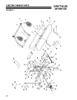
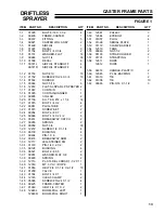
Page 14: ...12 DRIFTLESS SPRAYER CASTER FRAME PARTS FIGURE 1...
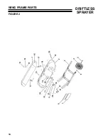
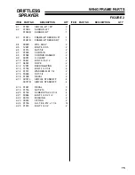
Page 16: ...14 DRIFTLESS SPRAYER WING FRAME PARTS FIGURE 2...
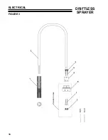
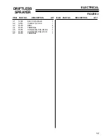
Page 18: ...16 DRIFTLESS SPRAYER ELECTRICAL FIGURE 3...
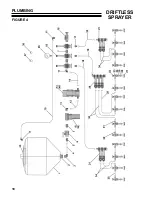
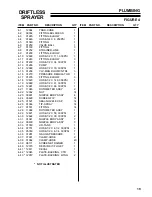
Page 20: ...18 DRIFTLESS SPRAYER PLUMBING FIGURE 4...
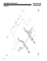
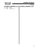
Page 22: ...20 DRIFTLESS SPRAYER ASSEMBLY FM MOUNT FIGURE 5...
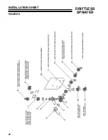
Page 24: ...22 DRIFTLESS SPRAYER INSTALLATION SHEET FIGURE 6...
Page 26: ...24 DRIFTLESS SPRAYER CASTER WHEEL ASSEMBLY FIGURE 7...


