4
DRIFTLESS
SPRAYER
GENERAL SPRAYING INFORMATION
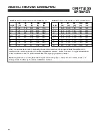
After the nozzles have been individually checked and matched, the sprayer should be calibrated to
determine the correct speed for the desired application volume. Refer to Table 1, for typical application
rates for different nozzles. Note nozzles listed are Spraying Systems nozzles.
Note: Tip pressure is usually less than the pressure at the pump. Losses occur in valves, hoses, etc.
Always check the flow by the above calibration method.
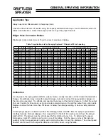
Table 2: Time in Seconds to Travel Distance of: Table 3: Time in Seconds to Travel a Distance of:
mph
10
(ft)
25
(ft)
50
(ft)
100
(ft)
200
(ft)
1
1.5
2
2.5
3
4
5
6.8
17.0
34.1
68.2
136
4.5
11.4
22.7
45.5
90.9
3.4
8.5
17.0
34.1
68.2
2.7
6.8
13.6
27.3
54.5
2.3
5.7
11.4
22.7
45.5
1.7
4.3
8.5
17.0
34.1
1.4
3.4
6.8
13.6
27.3
6
1.1
2.8
5.7
11.4
22.7
mph
10
(m)
25
(m)
50
(m)
100
(m)
200
(m)
1
36.0
90.0
180
360
720
1.5
24.0
60.0
120
240
480
2
18.0
45.0
90.0
180
360
2.5
14.4
36.0
72.0
144
288
3
12.0
30.0
60.0
120
240
4
9.0
22.5
45.0
90.0
180
5
7.2
18.0
36.0
72.0
144
6
6.0
15.0
30.0
60.0
120
Summary of Contents for 73-70675
Page 13: ...11 DRIFTLESS SPRAYER PARTS SECTION PARTS SECTION...
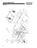
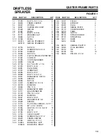
Page 14: ...12 DRIFTLESS SPRAYER CASTER FRAME PARTS FIGURE 1...
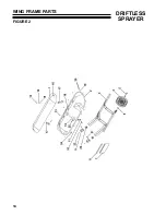
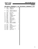
Page 16: ...14 DRIFTLESS SPRAYER WING FRAME PARTS FIGURE 2...
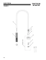
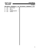
Page 18: ...16 DRIFTLESS SPRAYER ELECTRICAL FIGURE 3...
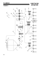
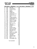
Page 20: ...18 DRIFTLESS SPRAYER PLUMBING FIGURE 4...
Page 22: ...20 DRIFTLESS SPRAYER ASSEMBLY FM MOUNT FIGURE 5...
Page 24: ...22 DRIFTLESS SPRAYER INSTALLATION SHEET FIGURE 6...
Page 26: ...24 DRIFTLESS SPRAYER CASTER WHEEL ASSEMBLY FIGURE 7...


