background image

INSTRUCTION MANUAL

999 1430.1

© 2003 Greenlee Textron

IM 1192 REV 1  10/03

Read and understand all of the instructions and
safety information in this manual before operating
or servicing this tool.

Swivels

Description

The Greenlee swivels, when used with a rope connector,
are intended for connecting the pull rope to the utility
product in an overhead or underground application.
The swivel permits rotation of the pull rope while protect-
ing the product from twisting.

• These swivels are not designed to run around bull

wheels.

• These swivels are not suitable for directional

drilling applications.

• These swivels are not intended for lifting appli-

cations.

Safety

Safety is essential in the use and maintenance of
Greenlee tools and equipment. This manual and any
markings on the tool provide information for avoiding
hazards and unsafe practices related to the use of this
tool. Observe all of the safety information provided.

Purpose of this Manual

This manual is intended to familiarize all personnel with
the safe operation and maintenance procedures for
Greenlee swivels.

Keep this manual available to all personnel.

Replacement manuals are available upon request at
no charge.

Summary of Contents for GREENLEE 39106

Page 1: ...ot designed to run around bull wheels These swivels are not suitable for directional drilling applications These swivels are not intended for lifting appli cations Safety Safety is essential in the use and maintenance of Greenlee tools and equipment This manual and any markings on the tool provide information for avoiding hazards and unsafe practices related to the use of this tool Observe all of ...

Page 2: ...Use recommended safe working limit For underground use and use in conduit the recommended safe working limit is 3 1 based on the ultimate load For overhead use the required safe working limit is 5 1 based on the ultimate load due to the higher risk of severe personal injury or property damage Failure to observe this warning could result in severe injury or death Never use a worn defective or incom...

Page 3: ...N 6 0 kN 22 mm 9 5 mm 7 9 mm 24 6 mm 11 1 mm 64 mm 86 mm 0 15 kg 39107 5 000 lb 3 000 lb 1 1 4 17 32 13 32 1 9 32 17 32 3 11 16 4 3 4 1 4 1 0 lb 22 kN 13 kN 32 mm 13 5 mm 10 3 mm 32 5 mm 13 5 mm 94 mm 121 mm 0 45 kg 39108 7 000 lb 4 200 lb 1 3 8 9 16 1 2 1 3 8 5 8 3 7 8 5 1 8 5 16 1 4 lb 31 kN 19 kN 35 mm 14 3 mm 12 7 mm 35 0 mm 15 9 mm 98 mm 130 mm 0 63 kg 39109 10 000 lb 6 000 lb 1 5 8 11 16 5 8...

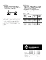
Page 4: ...e Check for axial and radial play in the bearings 2 Replace worn or bent clevis pins with original equipment manufacturer s pins Replacement kits consisting of two pins are available Replacement Pins To achieve rated strength always tighten attachment pins firmly before placing these swivels under load THIS PRODUCT IS NOT SERVICEABLE If swivel ceases to operate correctly replace with new one The o...

Reviews: