background image

RK1240 and RK1240C Crimping Tools

Greenlee / A Textron Company

4455 Boeing Dr. • Rockford, IL 61109-2988 USA • 815-397-7070

10

Step 4.  Installing the Ram

Assembly 

(refer to the Illustration)

1.  Lubricate the Die Retainer (4) and Die Release 

Button (2) with a Molybdenum Disulfide grease. 

Assemble them into the C-head and install Drive  

Pin (3). Add two drops of Loctite

®

 242

®

 Threadlocker 

to Screw (6), install Spring (5) from the top of the  

C-head and retain with Screw (6). Adjust the Screw 

(6) so that the Die Retainer (4) is flush with the head 

when the Die Release Button (2) is pressed.

2.  Inspect the external surface of the ram and the 

inside surface of the cylinder for nicks, gouges or 

other imperfections. Replace the ram or cylinder if 

necessary.

3.  Assemble Spring (11), Die Retaining Pin (10) and Die 

Release Button (12) to the Ram (15). Retain with the 

Roll Pin (9).

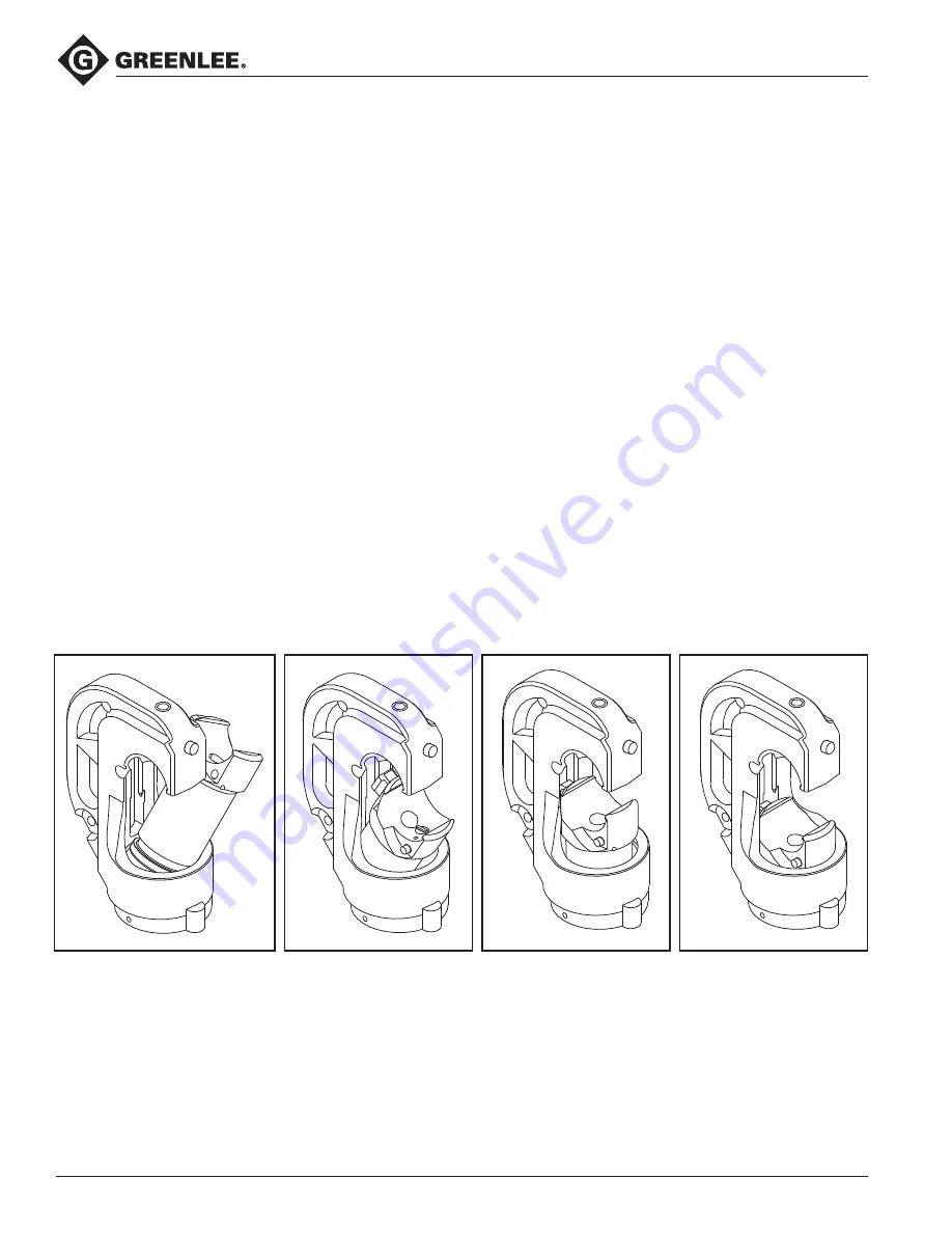
4.  Tilt and slide the ram (15) through the opening in  

the C-head (1). Align the T-shaped protrusion on the 

ram with the T-shaped groove in the C-head and 

assemble the ram to the head (see below).

5.  Slide the Washer (16) and Wiper (17) onto the  

Ram (15) as far as they will go. Place the U-cup Seal 

(21) on the Ram.

6.  Assemble the Extension Spring (19) to the two 

Spring Retainers (18,20). 

7.  Thread the Spring Retainer (20) into the base of the 

Cylinder (23), use a 5mm Allen wrench to tighten the 

spring retainer. 

8.  Lubricate the O-ring (22) and Backup Ring (21) and 

threads on the cylinder and C-head.

9.  Slide the ram assembly down the C-head and 

assemble into the cylinder (23) far enough for full  

O-ring and Backup ring engagement.

10.  Slip the cylinder into the base of the C-head and 

start threading them together. Continue to thread 

the cylinder into the C-head until the cylinder con-

tacts the C-head.

11.  Lock the C-head in place with the Set Screw (7) .
12.  Install Nylon Washer (14) and 8mm Screw (13) 

through the ram and tighten securely.

13.  Use Pipe Sealer and assemble the 3/8" NPT Pipe 

(24) to the 3/8 Coupler (25). Assemble to the 

cylinder.

Summary of Contents for Greenlee RK1240

Page 1: ... type Crimping Tools 99926989 2011 Greenlee Textron Inc IM 1337 REV 7 9 11 Read and understand all of the instructions and safety information in this manual before operating or servicing this tool Register this product at www greenlee com Serial Codes GAB and ADL ...

Page 2: ...ls and equipment This instruction manual and any markings on the tool provide information for avoiding hazards and unsafe practices related to the use of this tool Observe all of the safety information provided Purpose of this Manual This manual is intended to familiarize all personnel with the safe operation and maintenance procedures for the following Greenlee tools RK1240 Serial Code GAB RK1240...

Page 3: ...oiding the hazard Immediate hazards which if not avoided WILL result in severe injury or death Hazards which if not avoided COULD result in severe injury or death Hazards or unsafe practices which if not avoided MAY result in injury or property damage Read and understand all of the instructions and safety information in this manual before operating or servicing this tool Failure to observe this wa...

Page 4: ...ng debris or hydraulic oil Pinch points Keep hands away from closing dies Failure to observe this warning could result in severe injury or death Use proper die connector and wire combinations Mismatched components can result in an incomplete crimp Failure to complete a crimp could result in severe injury death or fire if a connection separates or if it has high electrical resistance Inspect tool a...

Page 5: ...ight 127 mm 5 Stroke with dies 42 mm 1 65 Die Type Standard U type Crimp Force 10 9 metric tons 12 tons Crimp Capacity 750 kcmil copper and aluminum lugs taps and splices Power Source Required 700 bar 10 000 psi RK1240 and RK1240C 1 Die Release Button 2 Die Release Button 3 Head Die Retaining Pin 4 Ram Die Retaining Pin 5 Hot Stick Adapter thread size 5 16 18 UNC 6 Hydraulic Coupling 3 8 threaded ...

Page 6: ... crimp Failure to complete a crimp could result in severe injury death or fire if a connection separates or if it has high electrical resistance Inspect tool and dies before use Replace any worn or damaged parts A damaged or improperly assembled tool could break and strike nearby personnel with suf ficient force to cause severe injury or death Do not operate crimping tool without dies in place Dam...

Page 7: ...ote When using KC12 type dies complete the number of crimps listed on the Connector Selection chart in this manual For other dies complete the number of crimps specified by the manufacturer 1 Prepare the cable by stripping off the appropriate amount of insulation 2 Select a connector that corresponds to the conduc tor and the application 3 Insert the conductor into the connector Position the conne...

Page 8: ...0 AWG White 2 KA12 250 22123 250 kcmil Red 2 KA12 300 22124 300 kcmil Blue 2 KA12 350 22125 350 kcmil Brown 2 KA12 400 22126 400 kcmil Green 3 KA12 500 22127 500 kcmil Pink 3 KA12 600 22128 600 kcmil Black 3 KA12 750 22129 750 kcmil Yellow 3 Connector Selection Tool Range 8 AWG to 750 kcmil When used with KC12 type dies this tool is cUL and UL classified for use with the following connector brands...

Page 9: ...evere injury or death Inspect tool and dies before use Replace any worn or damaged parts A damaged or improperly assembled tool could break and strike nearby personnel with suf ficient force to cause severe injury or death Do not operate crimping tool without dies in place Damage to the ram or crimping tool head may result Do not perform any service or maintenance other than as described in this m...

Page 10: ...h the opening in the C head 1 Align the T shaped protrusion on the ram with the T shaped groove in the C head and assemble the ram to the head see below 5 Slide the Washer 16 and Wiper 17 onto the Ram 15 as far as they will go Place the U cup Seal 21 on the Ram 6 Assemble the Extension Spring 19 to the two Spring Retainers 18 20 7 Thread the Spring Retainer 20 into the base of the Cylinder 23 use ...

Page 11: ...RK1240 and RK1240C Crimping Tools Greenlee A Textron Company 4455 Boeing Dr Rockford IL 61109 2988 USA 815 397 7070 11 Illustration 6 5 3 2 1 13 14 7 9 10 11 12 15 16 17 18 19 20 21 23 24 25 4 ...

Page 12: ...632 Washer steel 1 17 50053019 Wiper leather 1 18 50053345 Retainer spring 1 19 50053361 Spring extension 1 20 50053388 Retainer spring 1 21 90552067 Seal U cup 1 23 50053396 Cylinder 42 mm 1 24 50413642 Nipple pipe 3 8 NPT hex 1 25 50419411 Coupler hydraulic Parker 3010 3 1 50418341 Cap plastic 50487426 Decal warning 50054686 Carrying case metal 50054694 Lid liner warning 50054716 Lid liner instr...

Reviews: