background image

GB-21

GB

JACOBSEN FAIRWAY 405 Series CH

SAFETY AND OPERATORS MANUAL

7

OPERATION

7.6

MOWING

1.

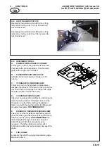
Activate joystick by pushing on the lower
half of the cutting unit switch.  Lower the
units with the cutting unit lift control.

2.

Ensure speed limiter is in mow position.

3.

Engage the cutting mechanism by
operating the floor mounted switch.

4.

Release the parking brake and begin
driving forward.

NOTE:

Always set the throttle to full for mowing,
even when the grass is heavy. When the
engine is labouring, reduce forward speed
by easing up on the FWD/REV foot pedal.

7.7

TO STOP THE ENGINE

1.

Disengage power to the cutting units with
the cutting unit switch.

2.

Remove foot from the FWD/REV pedal.

3.

Set the parking brake.

3.

Move the throttle control lever to the
SLOW position.

IMPORTANT: Turbocharged engines should be
allowed to idle for five minutes before switching off.
4.

Turn the ignition key to OFF.

7.8

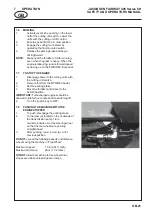
PUSHING THE MACHINE WITH THE
ENGINE STOPPED

1.

To push, disengage the parking brake.

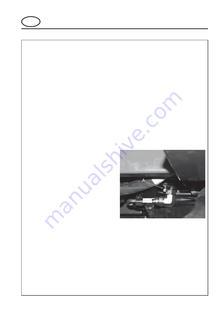
2.

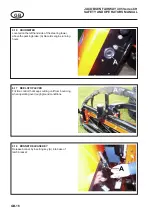
Turn screw (A) located on the underside of
the transmission pump 1 turn
counterclockwise. Set the steering wheel
so that the rear wheels are pointing
straight ahead.

3.

After pushing, return screw (A)  to it's
previous position.

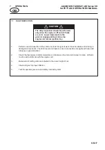
DO NOT exceed the following speeds and distance
when moving the machine in 'Free Wheel'.

Maximum Speed:

1.5 Km/Hr (1 mph)

Maximum Distance:

2Km (1 1/4 miles)

DO NOT allow the machine to free wheel down
slopes even when unloading down ramps.

Summary of Contents for Jacobsen Fairway 250

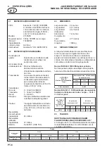
Page 1: ...parar conduzir afinar ou reparar a máquina Safety and Operation Manual Manual de Segurança e de Funcionamento WARNING If incorrectly used this machine can cause severe injury Those who use and maintain this machine should be trained in its proper use warned of its dangers and should read the entire manual before attempting to set up operate adjust or service the machine 24495G PT rev 0 RJ 100 1220...

Page 2: ... 2004 Ransomes Jacobsen Limited All Rights Reserved ...

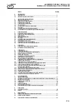
Page 3: ...6 CONTROLS 6 1 STARTER SWITCH 11 6 2 THROTTLECONTROL 11 6 3 STEERINGWHEELRAKEADJUSTMENT 11 6 4 TRACTIONFOOTPEDAL FORWARD REVERSE 11 6 5 FOOTPEDALNEUTRALLATCH 11 6 6 SPEEDLIMITER 12 6 7 PARKINGBRAKE 12 6 8 JOYSTICKUNITLIFT LOWERCONTROL 12 6 9 NARROWCUTCONTROL 13 6 10 UNITCOUNTERBALANCECONTROL 13 6 11 VARIABLECYLINDERSPEED 13 6 12 BACKLAPPINGLEVER 14 6 13 CUTTINGUNITSWITCHES 14 6 14 UNIT TRANSPORT S...

Page 4: ...with and strict adherence to the conditions of operation service and repair as specified by the manufacturer also constitute essential elements of the intendeduse Before attempting to operate this machine ALL operators MUST read through this manual and make themselves thoroughly conversant with Safety Instructions controls lubrication and maintenance Accident prevention regulations all other gener...

Page 5: ...s observe the Highway Code both on and off the roads Keep alert and aware at all times Watch out for traffic when crossing or near roadways Stop the blades rotating before crossing surfaces other than grass Remember that some people are deaf or blind and that children and animals can beunpredictable Keep travelling speeds low enough for an emergency stop to be effective and safe at all times in an...

Page 6: ...t to get hands and feet trapped when rotating cylinders Make sure that other people are not touching any cutting units as rotation of one cylinder can cause the others to rotate To reduce the fire hazard keep the engine silencer and battery compartments free of grass leaves or excessive grease Replace worn or damaged parts for safety When working underneath lifted parts or machines make sure adequ...

Page 7: ...It may also be used to alert against unsafe practices IMPORTANT Transport speed is for highway use only Never select transport speed on grass areas or uneven or unsurfaced roads or tracks The operating Instructions for the Cutting Units are contained in a separate Publication California Proposition 65 Engine Exhaust some of its constituents and certain vehicle components contain or emit chemicals ...

Page 8: ...IONLEVEL The machine was tested for whole body and hand arm vibration levels The operator was seated in the normal operating postion with both hands on the steering mechanism The engine was running and the cutting device was rotating with the machine stationary Standard ISO 5349 1986 Mechanical vibration Guidelines for the measurement and the assessment of human exposure to hand transmitted vibrat...

Page 9: ...Classification CE SF grades SAE 10W 30 Grease Shell Darina R2 or equivilant 4 7 CUTTINGPERFORMANCE 46 cuts per meter at 12 km hr with 7 knife cutting head units 72 cuts per meter at 12 km hr with 11 knife cutting head units 4 8 CUTTINGPERFORMANCE AREA 4 32 hectares hr at 12 km hr 10 67 acres hr at 7 5 mph 10 allowance is included for normal overlaps and turning at the end of each cut 4 SPECIFICATI...

Page 10: ...ijnen en Amendementen alsmede aan de verordeningen die deze omzetten in nationale wetgeving den Bestimmungen der folgenden Europa Richtlinien einschließlich aller Änderungen und Ergänzungen sowie den Vorschriften die diese in das nationale Recht umsetzen entspricht soddisfa quanto previsto dalle seguenti direttive ed emendamenti europei e dalle normative che li riportano in legge nazionale Overhol...

Page 11: ...ngen Rispetta il seguente standard armonizzato o requisiti tecnici Overholder følgende harmoniserede standardbestemmelser eller tekniske bestemmelser Uppfyller följande harmoniserade standard eller tekniska definitione täyttää seuraavat harmonisoidut standardit tai tekniset edellytykset Cumple con los siguientes estándares de hramonización o provisiones técnicas Está em conformidade com a norma ha...

Page 12: ...e ConsultTechnicalManualforService Procedures A903490 Do Not Remove Safety Shields While Engine is Running A911410 Danger of Explosion if the Battery Terminals are Short Circuited A911416 Maximum permitable working slope A911434 Caution Diesel Fuel 5 2 INSTRUCTIONDECALS Description A Diesel Fuel B Hydraulic Oil C Jacking Point D Cutting Unit Lift E Fwd Rev Traction Pedal F Cutter Engage G Weight T...

Page 13: ...ne speed NOTE Engine should be used at full speed 6 3 STEERINGWHEELRAKEADJUSTMENT The steering wheel is adjustable for rake The clamping release knob A is situated on the side of the control console on the left hand side To adjust turn the clamping knob anticlockwise to release and pivot the steering wheel backwards and forwards to obtain desired setting then lock in position by turning clamping k...

Page 14: ...orward A until it locks to set parking brake Release parking brake by pushing the brake pedal at the same time lever B is pulled up 6 8 JOYSTICKUNITLIFT LOWERCONTROL NOTE The joystick will not operate unless the mow switch see 6 13 item G is switched on The joystick can be operated in 4 directions 2 Axis A B C D A One touch lower Lower all cutting units B One touch raise Raise all cutting units Ne...

Page 15: ...d the normal setting is midway way between the maximum and minimum positions 6 CONTROLS 6 11 VARIABLECYLINDERSPEED Thespeedofrotationofthecuttingcylindersisadjustable bymeansofthehandwheel A situatedonthelefthand side of the operator Cylinder speed should be set to maximum in normal cutting conditions In very long growthconditions cylinderspeedshouldbereducedto obtainbestfinish cylinderspeedshould...

Page 16: ...lower units and depress foot switch A to start cutter rotation Push top of rocker switch to stop cutter unit rotation and de activate joystick Cutting units stop rotating automatically whenraised 6 12 BACKLAPPINGLEVER Sets reel rotational direction with three positions A forwardformowing B reverseforbacklapping and C neutral See the separate cutting unit operator s manual for an explanation of the...

Page 17: ...mes on while theengineisrunning thefanbeltmaybeslippingor broken or a fault in the electrical system is indicated and shouldbeinvestigated STOPIMMEDIATELY E ENGINEOILPRESSUREWARNINGLAMP Colourred onwhentheignitionisswitchedon andwill go out once the engine has started If the light comes on whiletheengineisrunning STOPIMMEDIATELYas this indicates that the engine oil pressure is too low Check the le...

Page 18: ...on the lefthand side of the steering tower above the parking brake A Records engine running hours 6 17 REELSTOPLEVER Friction control that keeps cutting unit from bouncing whenoperatingoverroughgroundconditions 6 18 BONNETRELEASEKEY Release bonnet by inserting key A into base of latch bracket ...

Page 19: ...2 Check the fuel supply radiator coolant level crankcase oil level and air cleaner is clean All fluids must be at the full mark with the engine cold 3 Make sure all cutting units are adjusted to the same height of cut 4 Check all tyres for proper inflation 5 Test the operator presence and safety interlock system The daily inspection should be performed only when the engine is off and all fluids ar...

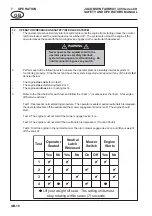
Page 20: ...1 Represents normal starting procedure The operator is seated pedal neutral latch is released the operators feet are off the pedals and the mower engagement device is off The engine should start Test 2 The engine must not start if the mower engage device is on Test 3 The engine must not start if the neutral latch is depressed Traction Pedal Test 4 Start the engine in the normal manner then turn mo...

Page 21: ...ted to bystanders and or damage to their property 6 Use discretion when mowing near gravel areas roadway parking areas cart paths etc Stones discharged from the implement may cause serious injuries to bystanders and or damage the equipment 7 Disengage the drive motors and raise the implements when crossing paths or roads Look out for traffic 8 Stop and inspect the equipment for damage immediately ...

Page 22: ... fully clockwise to the start position and operate the starter motor until the engine starts This should only take a few seconds 4 When the engine starts release the key immediately and it will return to the RUN position 5 If the engine does not start preheat the glow plugs and try again NOTES Warm engine When the engine is warm becauseofsurroundingtemperatureor recent operation step No 2 of the c...

Page 23: ... units with the cutting unit switch 2 Remove foot from the FWD REV pedal 3 Set the parking brake 3 Move the throttle control lever to the SLOW position IMPORTANT Turbochargedenginesshouldbe allowed to idle for five minutes before switching off 4 Turn the ignition key to OFF 7 8 PUSHINGTHEMACHINEWITHTHE ENGINESTOPPED 1 To push disengage the parking brake 2 Turn screw A located on the underside of t...

Page 24: ...seat can be slid backwards and forwards When in the desired position release the lever to locate in one of the pre set positions 3 BACKRESTADJUSTMENT The back rest has three preset positions To Adjust The position of the release lever is on the left hand side of the seat back rest C Move the lever upwards to move the upper part of the back rest forward Move the lever downwards to move the upper pa...

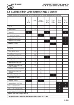
Page 25: ...y S k c o l r e t n I k c e h C z l e v e L t n a l o o C p u p o T k c e h C z r o t a r e p e S r e t a W n i a r D k c e h C z z e r u s s e r P e r y T k c e h C z l e v e L d i u l F c i l u a r d y H k c e h C z g u B y a B e n i g n E n a e l C k c e h C r o t a i d a R n e e r c S z s s e n t h g i T r o F s t l o B s t u N k c e h C z r o F s g n i t t i F c i l u a r d y H k c e h C s s ...

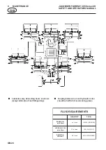
Page 26: ...z z z z z Coupling between reel and hydraulic motor should be half full of non tracking grease S T N E M E R I U Q E R D I U L F Y T I T N A U Q E P Y T L I O E N I G N E r e t l i f h t i w s e r t i L 4 6 G S F S E S 0 3 W 0 1 L I O C I L U A R D Y H r e t l i f h t i w s e r t i L 9 7 3 F S E C 0 3 W 0 1 R O T A I D A R T N A L O O C s e r t i L 8 6 E Z E E R F I T N A 0 5 ...

Page 27: ...ulic tank Oil must be filtered through a 25 micron filter before entering the hydraulic tank Cooling System Check coolant level in expansion tank the coolant level should be between the marks indicated on the expansion bottle Top up if neccessary using a 50 antifreezesolution Air Filter If working in dusty conditions the air filter element should be examined and cleaned replaced every 8 workinghou...

Page 28: ...of spares replacements or extra components which are not supplied or approved by us for the purpose The use of non recommended oil or lubricant nullifies the guarantee Damage through transport or normal wear does not come under the guarantee SALES SERVICE A network of authorised Sales and Service dealers has been established and these details are available from your supplier When service attention...

Page 29: ...ETA 11 6 3 REGULAÇÃODOVOLANTE 11 6 4 PEDALDETRACÇÃO 11 6 5 LINGUETADEPOSIÇÃONEUTRA 11 6 6 LIMITADORDEVELOCIDADE 12 6 7 TRAVÃODEESTACIONAMENTO 12 6 8 COMANDODESUBIDA DESCIDADAUNIDADEDE CORTEPORJOYSTICK 12 6 9 COMANDOPARACORTEESTREITO 13 6 10 COMANDODOEQUILÍBRIODASUNIDADESDECORTE 13 6 11 VELOCIDADEVARIÁVELDOSCILINDROS 13 6 12 ALAVANCADEINVERSÃODOSENTIDODEROTAÇÃO DO ROLO DE LÂMINAS 14 6 13 INTERRUPTO...

Page 30: ...fim a que se destina A estrita observância das condições de serviço assistência técnica e reparações conforme o construtor indica também constituem elementos essenciais da utilização adequada Antes de tentarem trabalhar com esta máquina TODOS os condutores TÊM de ler todo este manual e familiarizar se inteiramente com todos os aspectos relacionados com instruções de segurança comandos lubrificação...

Page 31: ...pre cuidadoso e esteja sempre com atenção Dê atenção ao trânsito ao atravessar estradas ou ao trabalhar na sua vizinhança Interrompaomovimentoderotaçãodaslâminas antes de atravessar zonas sem relva Lembre sedequehápessoassurdasoucegas e de que tanto as crianças como os animais podemtermovimentosimprevisíveis Mantenha as velocidades de deslocação suficientementereduzidasparapoderpararcom eficácia e...

Page 32: ...enha o cuidado de evitar que os cilindros em rotação apanhem as mãos e os pés Assegure se de que não há outras pessoas em contacto com as unidades de corte porque a rotação de um cilindro pode provocar a rotação dos outros Para reduzir o risco de incêndio mantenha os compartimentos do motor do silenciador e da bateria livres de relva folhas ou lubrificante em excesso Porrazõesdesegurança substitua...

Page 33: ...o níveis de corrente eléctrica suficientes para provocar queimaduras ATENÇÃO A fuga de fluido hidráulico sob pressão podepenetrarnapeleeprovocarferimentos graves Em tais casos deve se procurar assistência médica de imediato ATENÇÃO NÃO TRABALHAR COM A MÁQUINA EM TALUDESDEINCLINAÇÃOSUPERIORA15 ATENÇÃO Proposta 65 da Califórnia O escape do motor alguns dos seus componentes e certos componentes do ve...

Page 34: ...moldado de alta resistência com calhas com secção de caixa Accionamentoda unidade de corte Motores hidráulicos de deslocamentoconstante directamenteacopladosàunidade de corte Transmissão Accionamento permanente às 4 rodas Bomba de deslocamento variáveldeacoplamentodirecto para motores das rodas de acoplamento directo de 475 cm3 à frente e 343 cm3 atrás Velocidades De corte 0 12 km h AVANÇO Transpo...

Page 35: ...nte a A P I Classificação graus CE SF qualidades SAE 10 W 30 Massalubrificante ShellDarinaR2 ouequivalente 4 7 RENDIMENTODECORTE 46 cortes por metro a 12 km h com cabeças de corte com 7 lâminas 72 cortes por metro a 12 km h com cabeças de corte de 11 lâminas 4 8 RENDIMENTODECORTE ÁREA 4 32 hectares hora a 12 km h Incluindo 10 de margem para sobreposições normais e inversões de marcha no final de c...

Page 36: ...Richtlijnen en Amendementen alsmede aan de verordeningen die deze omzetten in nationale wetgeving den Bestimmungen der folgenden Europa Richtlinien einschließlich aller Änderungen und Ergänzungen sowie den Vorschriften die diese in das nationale Recht umsetzen entspricht soddisfa quanto previsto dalle seguenti direttive ed emendamenti europei e dalle normative che li riportano in legge nazionale O...

Page 37: ...mmungen Rispetta il seguente standard armonizzato o requisiti tecnici Overholder følgende harmoniserede standardbestemmelser eller tekniske bestemmelser Uppfyller följande harmoniserade standard eller tekniska definitione täyttää seuraavat harmonisoidut standardit tai tekniset edellytykset Cumple con los siguientes estándares de hramonización o provisiones técnicas Está em conformidade com a norma...

Page 38: ...cessos de assistência A903490 Não retire painéis de segurança com o motor a trabalhar A911410 Perigo de explosão se os terminais da bateriaforemcurto circuitados A911416 Declive máximo permitido durante o trabalho A911434 Cuidado gasóleo 5 2 ETIQUETASCOMINSTRUÇÕES Descrição A Gasóleo B Óleohidráulico C Ponto de aplicação para o macaco D Subida da unidade de corte E Pedaldetracçãoavanço recuo F Eng...

Page 39: ...la para si NOTA O motor deve trabalhar no regime máximo 6 3 REGULAÇÃODOVOLANTE A inclinação do volante é regulável O manípulo A de soltar o bloqueio está localizado ao lado da consola de comando no lado esquerdo Para regular rode o manípulo no sentido inverso para soltar e incline o volante para trás e para a frente até obter a posição desejada Seguidamente bloqueie rodando o manípulo no sentido d...

Page 40: ...rente até prender Para soltar o travão de estacionamento carregue no pedal de travão ao mesmo tempo que puxa a alavanca B para cima 6 8 COMANDODESUBIDA DESCIDADA UNIDADEDECORTEPORJOYSTICK NOTA O joystick só actua se o interruptor de corte darelva ver6 13 pontoG seencontrarligado O joystick pode ser comandado em 4 sentidos 2 eixos A B C D A Um toque para descida Descida de todas as unidades de cort...

Page 41: ...ntido inverso para aumentar o peso da unidade de corte sobre o solo Uma pressão elevada reduz a possibilidade da unidade de corte se adaptar às ondulações do terreno Ao cortar terreno plano a regulação normal é na posição média entre as posições máxima e mínima 6 11 VELOCIDADEVARIÁVELDOSCILINDROS A velocidade de rotação dos cilindros de corte é regulável por meio do volante A situado ao lado esque...

Page 42: ...tra Leia o manual de instruções da unidade de corte para o processo de inversão do sentido de rotação do rolo 6 13 INTERRUPTORESDAUNIDADEDECORTE Para começar a cortar assegure se de que o limitador de velocidade se encontra na posição de corte e de que as unidades foram descidas Carregue no botão do interruptor de balancé G e carregue no interruptor de pé A Carregue no topo do interruptor de balan...

Page 43: ...umvalorpreviamente determinado Sealâmpadaacender deve separara máquina desengatar as unidades de corte travar com o travão de estacionamento e desligar o motor D LÂMPADADEAVISODECARGA De cor vermelha acende quando se liga a ignição e apaga quando o motor arranca Se continuar acesa depois do motor começar a trabalhar é porque a correiadaventoinhapodeestaraescorregarouaté mesmo partida ou então indi...

Page 44: ...por cima do travão de estacionamento A Regista as horas de serviço do motor 6 17 ALAVANCADEPARAGEMDOROLODE LÂMINAS Comando por atrito que evita que a unidade de corte oscile durante o trabalho em solo irregular 6 18 CHAVE DE SOLTAR A TAMPA DO MOTOR Para soltar a tampa do motor introduza a chave A na base do suporte da lingueta 6 COMANDOS ...

Page 45: ... combustível o nível do refrigerante do radiador o óleo da cambota e o indicador de depurador de ar Todos os fluidos têm de se encontrar no traço de marcação cheio com o motor frio 3 Certifique se de que todos os dispositivos de corte estão regulados para a mesma altura de corte 4 Verifique a pressão dos pneus 5 Teste o sistema de presença do operador e interlock de segurança A inspecção diária só...

Page 46: ...nta o processo normal de arranque O operador está sentado no banco a lingueta de posição neutra do pedal é solta os pés do operador estão fora dos pedais e o dispositivo de engatedocorta relvaestádesligado Omotordeveráarrancar Teste 2 O motor não deve arrancar se o dispositivo de engate do corta relva estiver ligado Teste 3 O motor não deve arrancar se a lingueta de posição neutra estiver premida ...

Page 47: ...a cuidado ao cortar a relva junto de zonas com gravilha estrada parques de estacionamento acessos para automóveis etc As pedras projectadas pelo equipamento podem provocar ferimentos graves em pessoas próximas e ou danificar o equipamento 7 Desengate os motores de accionamento e levante os equipamentos quando atravessar passeios ou estradas Tenha cuidado com o tráfego 8 Pare e inspeccione o equipa...

Page 48: ...r trabalhado pouco antes pode se eliminar o passo 2 do arranque do motor a frio não há necessidade de fazer o pré aquecimento das velasdeincandescência Se o motor não arrancar ao fim de duas tentativas compré aquecimento se necessário aguarde 20 segundos e tente de novo O motor de arranque nunca deve ser accionado continuamente durante mais de 30 segundosporquepodeavariar 7 5 CONDUÇÃO Soltar o tra...

Page 49: ... de corte por meio do respectivo interruptor 2 Retire o pé do pedal AVANÇO RECUO 3 Accione o travão de estacionamento 4 Coloque a alavanca de comando da borboleta na posição SLOW LENTO IMPORTANTE Motorescomturbocompressor devemtrabalhardurantealgunsminutosno mínimo antes de serem desligados 5 Rode a chave de ignição para a posição OFF 7 8 EMPURRARAMÁQUINACOMOMOTOR PARADO 1 Para empurrar solte o tr...

Page 50: ...nco este pode ser deslocado para trás e para a frente Logo que esteja na posição desejada largue a alavanca para fixar numa das posiçõespré marcadas 3 REGULAÇÃODASCOSTASDOBANCO Para as costas do banco há três posições pré definidas Para regular A alavanca de soltar está localizada à esquerda das costas do banco C Puxe a alavanca para cima para fazer avançar a parte superior das costas Empurre a al...

Page 51: ...o d a g r u p o ã ç a c i f i r e V a u g á z z s u e n p s o d o ã s s e r p a d o ã ç a c i f i r e V z o d i u l f o d l e v í n o d o ã ç a c i f i r e V o c i l u á r d i h z r o t o m o d a n o z a d a z e p m i l o ã ç a c i f i r e V r o d a i d a r o d e o ã ç c e t o r p e d l e n i a p o d z e s a c r o p e d o t r e p a o d o ã ç a c i f i r e V s a h l i v a c z s e õ ç i n r a u g s ...

Page 52: ...O C I L U Á R D I H o r t l i f m o c s o r t i l 9 7 3 F S E C 0 3 w 0 1 E T N A R E G I R F E R O A R A P R O D A I D A R s o r t i l 8 6 e d 0 5 E T N A L E G N O C I T N A z z z z z Lubrifique de 40 em 40 horas de serviço nos locais indicados pelas setas excepção lubrifique diariamente todas as guarnições do rolo z z z z z O acoplamento entre o rolo e o motor hidráulico deve estar meio cheio d...

Page 53: ...través de um filtro de 25 micra antes de entrar no reservatório hidráulico Sistema de refrigeração Verifiqueoníveldorefrigerantenovasode expansão esse nível deve situar se entre os traços de marcação indicados no vaso de expansão Ateste se necessário com uma solução anticongelante a 50 Filtro do ar Quando se trabalha com muito pó o elemento do filtro tem de ser examinado e limpo substituído ao fim...

Page 54: ...mal ou à instalação de peças acessórias sobressalentes ou componentes extra que não sejam fornecidos ou aprovados por nós para o fim em causa O uso de óleos ou lubrificantes não recomendados anula a garantia Danos provocados por transporte ou desgaste normal não são cobertos pela garantia VENDAS E ASSISTÊNCIA Foi criada uma rede de vendedores e postos de assistência autorizados e o seu fornecedor ...

Page 55: ......
Page 56: ... dealer network and factory trained technicians backed by Ransomes Jacobsen Parts Xpress provide reliable high quality product support World Class Quality Performance and Support O equipamento de Ransomes Jacobsen Limited é construído segundo padrões exactos garantidos pela atribuição de ISO 9001 a todos os nossos centros de produção Rede mundial de distribuidores e técnicos formados na fábrica ap...

Reviews: