
PT-13
PT
JACOBSEN FAIRWAY 405 Série CH
MANUAL DE SEGURANÇA E DO OPERADOR
6
COMANDOS
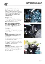
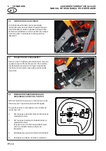
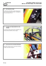
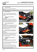
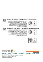
6.9
COMANDO PARA CORTE ESTREITO
Quando o interruptor ‘G’ é mantido na posição ‘F’,
as unidades 6 e 7 sobem em conjunto.
Quando o interruptor ‘G’ está na posição ‘E’, as
unidades 6 e 7 estão desligadas e outros
movimentos do joystick só comandam as unidades
1 até 5.
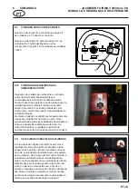
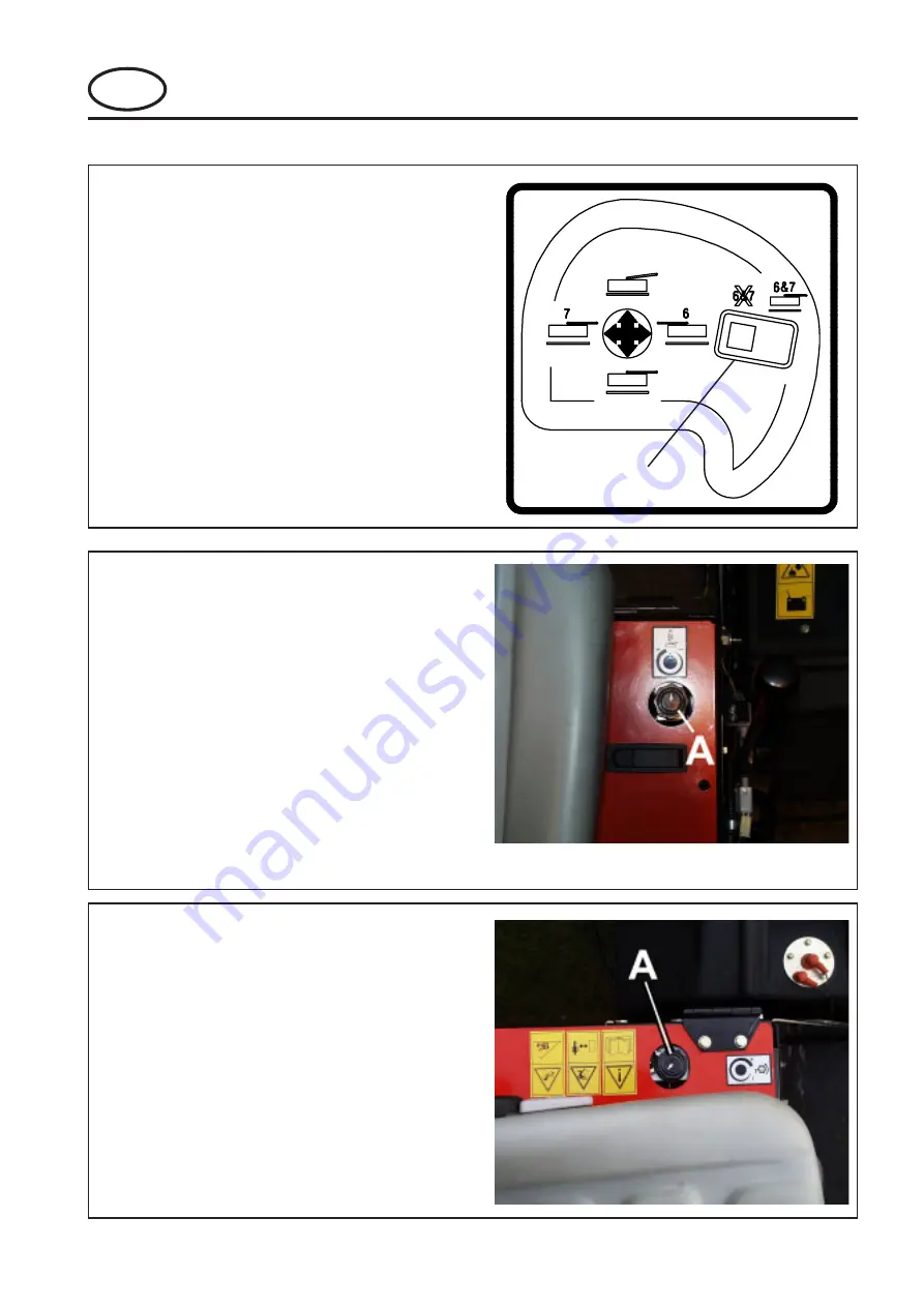
6.10
COMANDO DO EQUILÍBRIO DAS
UNIDADES DE CORTE
A pressão da unidade de corte sobre o solo pode
variar dentro de determinados limites e é
comandada pelo volante (A) localizado ao lado
direito do banco do operador e perto da alavanca de
subida/descida. O volante é rodado no sentido
directo para reduzir o peso da unidade de corte
sobre o solo, melhorando assim a possibilidade de
subida de taludes.
O volante é rodado no sentido inverso para aumentar
o peso da unidade de corte sobre o solo. Uma
pressão elevada reduz a possibilidade da unidade de
corte se adaptar às ondulações do terreno. Ao
cortar terreno plano, a regulação normal é na
posição média entre as posições máxima e mínima.
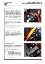
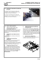
6.11
VELOCIDADE VARIÁVEL DOS CILINDROS
A velocidade de rotação dos cilindros de corte é
regulável por meio do volante (A) situado ao lado
esquerdo do operador. Para as condições normais
de corte, a velocidade do cilindro deve ser regulada
para o máximo. Se a relva estiver muito comprida, a
velocidade do cilindro deve ser reduzida para se
obter o melhor acabamento; a velocidade do cilindro
também deve ser reduzida quando a relva é muito
curta ou quando a relva está seca, a fim de se
reduzir o desgaste excessivo do cilindro e da lâmina
fixa. Rode o volante no sentido do movimento dos
ponteiros do relógio para aumentar a velocidade do
cilindro e no sentido contrário para a reduzir.
A
B
C
D
E
F
G
Summary of Contents for Jacobsen Fairway 250
Page 2: ... 2004 Ransomes Jacobsen Limited All Rights Reserved ...
Page 55: ......


