GB-4
•
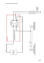
Disconnect the left hand marker lamp and reconnect to the kit harness as shown on faceing page.
•
Run the battery wires along the main battery cables . If fitted, make sure the positive (RED end)
cable is fed inside the rubber terminal boot. Connect the kit harness to the battery.
•
Connect the Working lamp electrical cable to the kit harness.
•
Test the lamp by turning on the ignition and pressing the light switch. If the light does not come on
turn off the ignition and check that the connections have been made cleanly and correctly.
•
Replace the side cover and the bonnet. Make sure that none of the wires are trapped in the hinge.
•
When assembled adjust the angle of the working lamp to shine on the working area.
Care must be taken around the battery to
ensure that it is not short circuited
CAUTION
Summary of Contents for RANSOMES LMAB643
Page 2: ...2000 Textron Inc All Rights Reserved...
Page 7: ...GB 5 WORKING LAMP KIT SCHEMATIC...
Page 8: ......
Page 13: ...F 5 SCHEMA DE PRINCIPE DU KIT DU FEU DE TRAVAIL...
Page 14: ......
Page 19: ...NL 5 SCHAKELSCHEMAWERKLAMPSET...
Page 20: ......
Page 25: ...D 5 SCHEMATISCHEDARSTELLUNGDERARBEITSLAMPE...
Page 26: ......
Page 31: ...I 5 SCHEMA DEL KIT DELLA LAMPADA DI LAVORO...
Page 32: ......
Page 37: ...DK 5 OVERSIGTOVERARBEJDSLYGT...
Page 38: ......
Page 43: ...S 5 KOPPLINGSSCHEMAF RARBETSBELYSNING...
Page 44: ......
Page 49: ...SF 5 TY SKENTELYLAMPPUTARPEISTONKAAVIO...
Page 50: ......
Page 55: ...E 5 ESQUEMA DEL JUEGO DE FOCO DE TRABAJO...
Page 56: ......
Page 61: ...P 5 ESQUEMA DO KIT DO FAROL DE TRABALHO...
Page 64: ......


