background image


27 


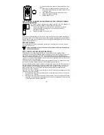
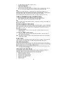
To install and replace the batteries, please follow the steps 
below: 
1. 

Insert finger or other solid object in the space at the 
bottom center of the battery compartment and lift up to 
remove the cover. 

2. 

Insert batteries observing the correct polarity (see 
battery compartment marking). 

3. 

Replace battery cover. 


HOW TO INSTALL AND REPLACE BATTERIES IN THE OUTDOOR THERMO-
HYGRO TRANSMITTER 

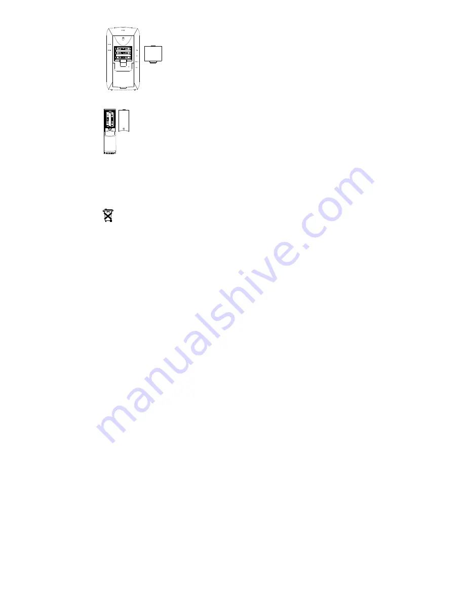
The outdoor Thermo-hygro transmitter uses 2 x AA IEC LR6, 1.5V batteries. To 
install and replace the batteries, please follow the steps below: 
1. 

Remove the battery cover at the front side with a small screwdriver. 

2. 

Insert the batteries, observing the correct polarity (see battery 
compartment marking). 

3. 

Replace the battery cover on the unit. 


Note: 

In the event of changing batteries in any of the units, all units need to be reset by following the 
setting up procedures. This is because a random security code is assigned by the transmitter at 
start-up and this code must be received and stored by the Weather Station in the first 3 minutes 
of power being supplied to it. 


BATTERY CHANGE: 

It is recommended to replace the batteries in all units on an annual basis to ensure o ptimum 
accuracy of these units. 


Please participate in the preservation of the environment. Return used batteries 
to an authorised depot. 


DCF-77 RADIO CONTROLLED TIME RECEPTION: 

The time base for the radio controlled time is a Cesium Atomic Clock operated by the 
Physikalisch Technische Bundesanstalt Braunschweig which has a time deviation of less than 
one second in one million years.  The time is coded and transmitted from Mainflingen near 
Frankfurt via frequency signal DCF-77 (77.5 kHz) and has a transmitting range of approximately 
1,500 km. Your radio-controlled Weather Station receives this signal and converts it to show the 
precise time in summer or wintertime. 
The quality of the reception depends greatly on the geographic location. In normal cases, th ere 
should be no reception problems within a 1,500km radius around Frankfurt. 


After the temperature and humidity reception is completed in initial setup, the DCF tower icon in 
the clock display will start flashing in the upper right corner of the first section of the LCD. This 
indicates that the clock has detected the presence of a radio signal and is trying to receive it. 
When the time code is received, the DCF tower becomes permanently lit and the radio-
controlled time will be displayed. 
If the tower icon flashes, but does not set the time or the DCF tower does not appear at all, then 
please take note of the following: 


Recommended distance to any interfering sources like computer monitors or TV sets is a 
minimum of 1.5 - 2 meters. 


Within ferro-concrete rooms (basements, superstructures), the received signal is naturally 
weakened. In extreme cases, please place the unit close to a window and/or point its front 
or back towards the Frankfurt transmitter. 


Summary of Contents for IQ-WS 35.1040

Page 1: ...ntelligent Weather Station together with the optimum benefit of all its features FEATURES The Intelligent Weather Station DCF 77 Radio controlled time with manual setting option DCF reception ON OFF u...

Page 2: ...after 3 minutes the batteries will need to be removed from both units and reset from step 1 4 The Weather Station can receive up to 3 remote Thermo hygro transmitters If you have purchased additional...

Page 3: ...ime base for the radio controlled time is a Cesium Atomic Clock operated by the Physikalisch Technische Bundesanstalt Braunschweig which has a time deviation of less than one second in one million yea...

Page 4: ...midity record Combine with the CH key to re detect a new transmitter in displayed channel Stop the alarm during the time alarm or weather alarm ringing Back light ON CH key Channel key Select channel...

Page 5: ...ather alarm ringing Back light on Reset all MIN MAX records ALM TIME key Enter the alarm time setting mode Stop the alarm during the time alarm or weather alarm ringing Back light on ALM Data key Ente...

Page 6: ...unit setting Air pressure unit setting Relative pressure value setting Language display setting Outdoor temperature in C or F Indoor general alarm icon Seconds display Indoor relative humidity in RH...

Page 7: ...firm with the SET key and enter the Manual Time setting MANUAL TIME SETTING In case the Weather Station cannot detect the DCF signal for example due to disturbances transmitting distance etc the time...

Page 8: ...the DCF time reception function is turned OFF manually the clock will not perform any reception of the DCF time as long as the DCF OFF function is activated The DCF reception icon will not be display...

Page 9: ...the manual setting anytime during the manual setting modes press the CH key anytime or wait for automatic timeout The mode will return to normal time display TIME ALARM SETTING The alarm time can be...

Page 10: ...y to set the alarm value 3 Press the SET key to confirm and enter the HIGH indoor temperature alarm setting IV If no LOW indoor temperature setting is needed please press the ALM DATA key to enter the...

Page 11: ...ly be set for channel 1 transmitter To set the HIGH outdoor temperature alarm default OFF I Buzzer ON OFF alarm sounding 1 Press the ALM STOP key to set buzzer ON OFF The icon will appear if the buzze...

Page 12: ...n the LOW outdoor humidity alarm setting there are optional sub settings Note The outdoor humidity alarm can only be set for channel 1 transmitter To set the LOW outdoor humidity alarm default OFF I B...

Page 13: ...will be shown in normal display when the weather alarm is set ON To exit the weather alarm setting mode anytime press the CH key or wait for automatic timeout The mode will return to normal time displ...

Page 14: ...m icon will flash when the outdoor temperature and humidity alarm occurs To switch off the general alarm icon press the ALM DATA key Additionally the trigged alarm value and time will then be displaye...

Page 15: ...ainy icon since the icons are already at their extremes The icons displayed forecasts the weather in terms of getting better or worse and not necessarily sunny or rainy as each icon indicates For exam...

Page 16: ...sections of the sections of the LCD show the relative air pressure and the air pressure history The reference relative air pressure hPa can be set between 960 to 1040hPa See Relative pressure value se...

Page 17: ...mperature the reception indicator the minimum or maximum reading A number in the bottom part will also be shown if more than one transmitter has been used TOGGLING BETWEEN MIN MAX INDOOR AND OUTDOOR R...

Page 18: ...learned again by entering the channel re learn mode To re learn ALL channels 1 Press and hold the CH key for 3 seconds outdoor reception signal will show next to channel display To re learn the CURRE...

Page 19: ...xx xx MinTemp xx x C Heute xx xx MinTemp xx x C Aujourdhui xx xx Snowfall Index 65 Schnee Index 65 Neige Index 65 Probability of snowfall Index 75 Index 75 Index 75 Fog Index 80 Nebel Index 80 Brouill...

Page 20: ...or window frames 3 Using other electrical products such as headphones or speakers operating on the same signal frequency 433MHz may prevent correct signal transmission and reception 3 Neighbours usin...

Page 21: ...pts to the units Return it to their original point of purchase for repair by a qualified engineer Opening and tampering with the units may invalidate their guarantee Do not expose the units to extreme...

Page 22: ...designed to be used in the home as indication of the future weather and is not 100 accurate Weather forecasts given by this product should be taken only as an indication and not as being totally accur...

Reviews: