©Copyright Task Force Tips LLC 2014-2021
13
LIA-208 May 19, 2021 Rev05
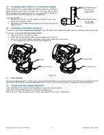
5.2 MOUNTING THE DISPLAY ENCLOSURE
Select proper location for display. A full size template is shown in 11.0 TEMPLATES.
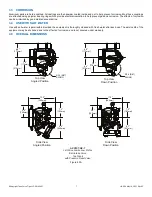
5.3 ELECTRIC INSTALLATION AND WIRING
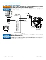
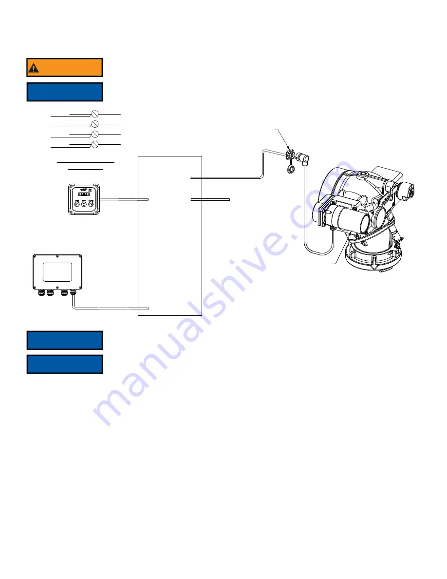
Figure 5.3
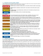
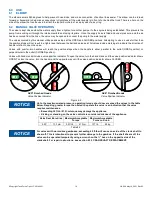
WARNING
This device is not rated as ignition proof, explosion proof, or intrinsically safe. Use only in locations
with adequate ventilation and no hazard of flammable vapor buildup.
NOTICE
Red (+) and black (-) wires must be connected to a 12 or 24 VDC protected circuit from the truck’s
power distribution center.
NOTICE
Cable is gel filled to prevent moisture wicking into the enclosure. Gel is non-hazardous and should
be wiped from conductors with a rag.
NOTICE
To avoid excessive voltage drop at the valve motor, do not lengthen factory supplied receptacle
cable. Power cable selection is critical. Voltage measured less than 10 volts at the valve motor while
operating will produce irradic operation.
Electric Motor
Jumbo Low Profile
Ball Intake Valve RC
Plug
Dust Cap
Interface Box
(optional)
Receptacle
Multiple operator stations may be installed.
All communication pairs (blue & white) and
power pairs (red & black) must be connected
in terminal box or another interface box.
BIV Operator
Station
Installer Supplied
Terminal Box or Optional
Interface Box Can Be Used
30 FT (9M) Maximum
Installer
Supplied
Power Cable
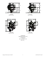
White
Blue
Black
Red
White
Blue
Black
Red
Red
Black
Blue
White
Typical Terminal Box
Connections

