©Copyright Task Force Tips LLC 2014-2021
15
LIA-208 May 19, 2021 Rev05
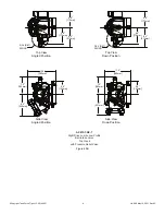
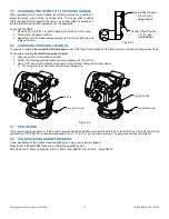
5.5 CHANGING THE OFFSET OF THE CRANK HANDLE
When equipped with a crank handle, two offset positions are available to
adjust the swing radius of the crank and knob. The longer offset position
offers reduced effort to operate the valve. The shorter offset is available to
avoid interference with other equipment on the apparatus.
To change the offset:
1. Remove two 1/4”-20 x 1/2” button head cap screws from the crank.
2. Place crank in desired position.
3. Apply blue Loctite thread locking compound to all screw threads, and
replace screws.
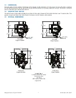
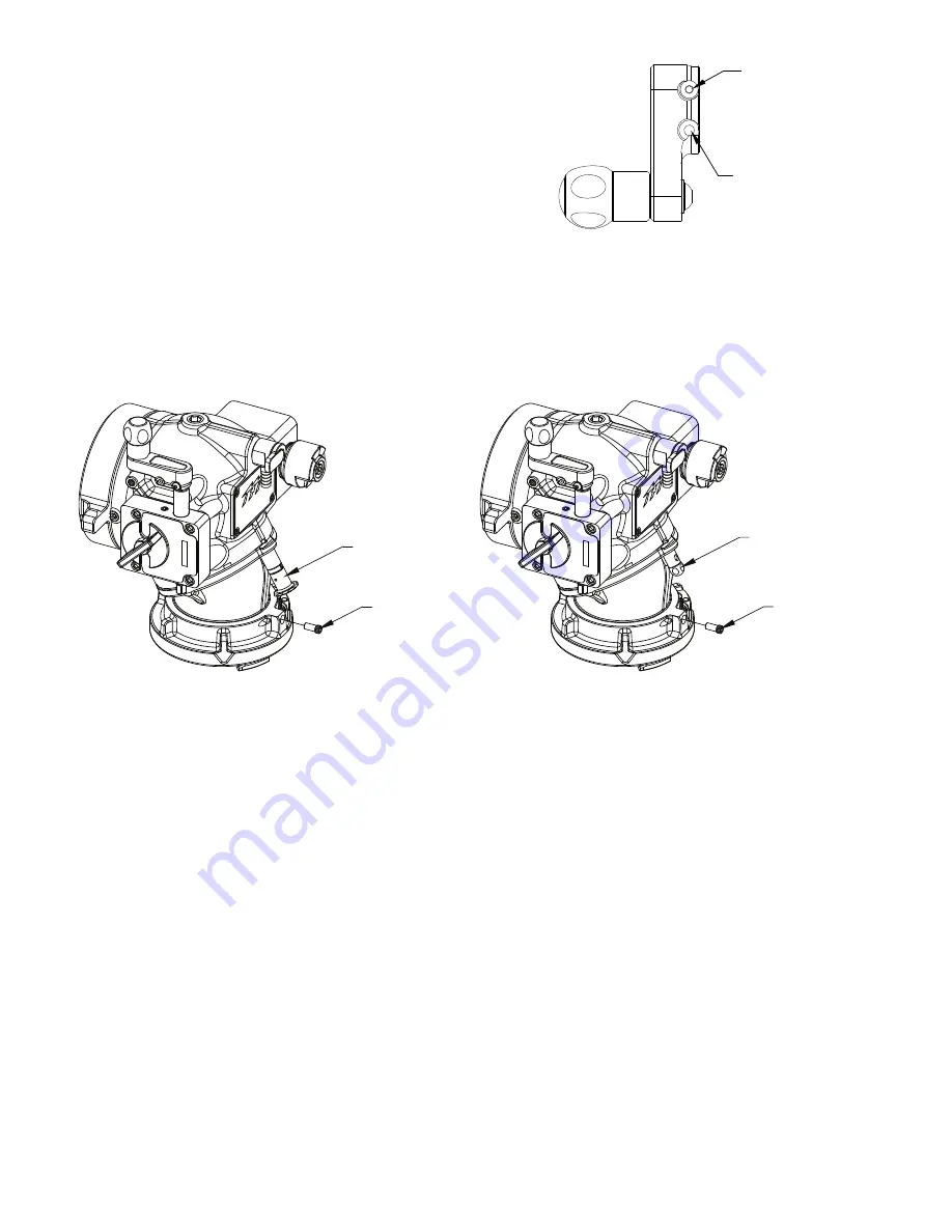
5.6 CHANGING COUPLING LOCK-OUT
To change a coupling
from rigid to full time swivel
, use a 7/32” hex driver to back out the lockout screw until the coupling moves freely.
To change a coupling
from full time swivel to rigid
:
1. Align the pull pin in the elbow to vertical.
2. Rotate the coupling until the lockout screw is aligned with the pull pin.
3. Use a 7/32” hex driver to tighten the lockout screw into the lockout divot in the elbow.
A. Do not tighten the screw onto the polymer bearing strip.
Figure 5.6
5.7 PEG OPTION
If total overall depth is critical, or if the pull pin remains hidden behind the valve and is hard to find, the Pull Pin can be replaced with an
optional Peg (TFT #A1576) to reduce overall depth from 11.3” to 10.4” on top crank versions. The peg does not lock into detents.
5.8 STORZ SUCTION GASKET REQUEST
If your application of this product requires drafting, you may need a suction gasket.
Please call 1-800-348-2686 to receive a free suction gasket by mail.
Part Numbers: 4” Storz- item #A4216-KIT, 5” Storz - item #A4221-KIT, 6” Storz - item #A4273
Longer Offset Position
2.6" [67 mm]
Swing Radius
Shorter Offset Position
1.6" [41 mm]
Swing Radius
Figure 5.5
Lock-Out Screw
Pull Pin
Lock-Out Screw
Peg (Optional)

