background image

Page 16

Indoor Unit 

Installation

4.  Connect the indoor unit’s  refrigerant piping

to the connective piping that will join the
indoor and outdoor units. Refer to the

Refrigerant Piping Connection 

section

of this manual for detailed instructions.

5. Based on the position of the wall hole

relative to the mounting plate, determine the

necessary angle of your piping.

6. Grip the refrigerant piping at the base of the

bend.

7. Slowly, with even pressure, bend the piping

towards the hole. 

Do not 

dent or damage the

piping during the process.

Step 5:


Connect drain hose

By default, the drain hose is attached to the left-

hand side of unit (when you’re facing the back 

of the unit). However, it can also be attached to 

the right-hand side. 
1.  To ensure proper drainage, attach the drain

hose on the same side that your refrigerant

piping exits the unit.

2.  Attach drain hose extension (purchased

separately) to the end of drain hose.

3.  Wrap the connection point firmly with Teflon

tape to ensure a good seal and to prevent

leaks.

4.  For the portion of the drain hose that will

remain indoors, wrap it with foam pipe

insulation to prevent condensation.

5.  Remove the air filter and pour a small amount

of water into the drain pan to make sure that

water flows from the unit smoothly.

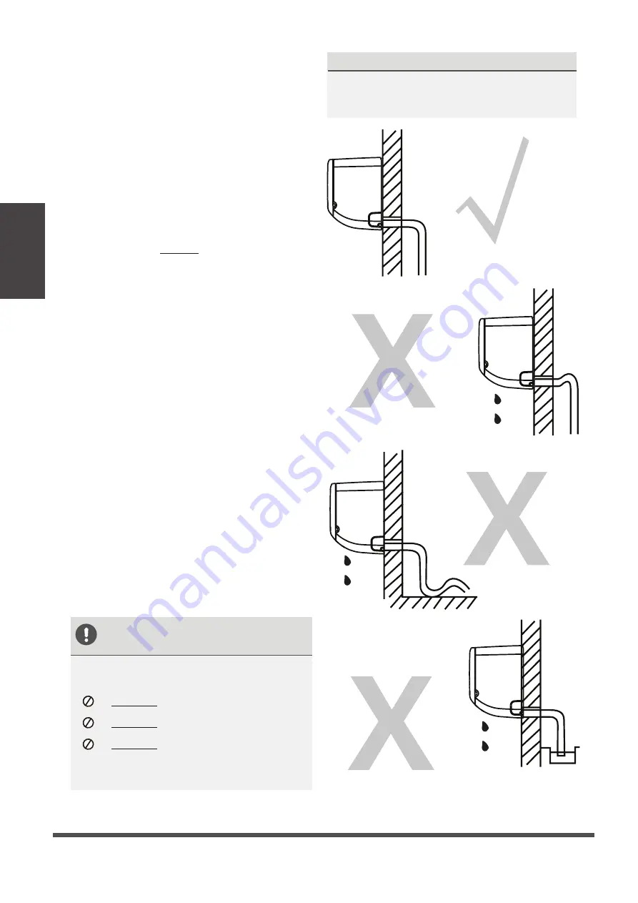
 NOTE ON DRAIN HOSE 
 PLACEMENT 

Make sure to arrange the drain hose 

according to 

Fig. 3.9

DO NOT 

kink the drain hose.


DO NOT


create a water trap.


DO NOT 

put the end of drain hose in

water or a container that will collect 
water.

PLUG THE UNUSED DRAIN HOLE

To prevent unwanted leaks you must plug 

the unused drain hole with the rubber plug 

provided.

CORRECT 

Make sure there are no 

kinks or dent in drain 

hose to ensure proper 

drainage.

NOT CORRECT

Kinks in the drain hose 

will create water traps.

NOT CORRECT

Do not place the end 

of the drain hose in 

water or in containers 

that collect water. This 

will prevent proper 

drainage.

NOT CORRECT

Kinks in the drain hose 

will create water traps.

Fig. 3.9

Fig. 3.10

Fig. 3.11

Fig. 3.12

Summary of Contents for CS78421-548-754

Page 1: ... Read this manual carefully before installing or operating your new air conditioning unit Make sure to save this manual for future reference SPLIT TYPE ROOM AIR CONDITIONER Installation Manual Dream Inverter Series All Model Numbers ...

Page 2: ... 4 Prepare refrigerant piping 14 5 Connect drain hose 15 6 Connect signal cable 17 7 Wrap piping and cables 18 8 Mount indoor unit 18 Outdoor Unit Installation 20 8 1 Select installation location 20 2 Install drain joint 21 3 Anchor outdoor unit 22 4 Connect signal and power cables 23 Safety Precautions 4 0 1 5 Accessories 6 2 4 Unit Parts 10 3 Installation Summary Indoor Unit ...

Page 3: ...gerant Piping 25 1 Cut pipe 25 2 Remove burrs 26 3 Flare pipe ends 26 4 Connect pipes 27 Air Evacuation 29 1 Evacuation Instructions 29 2 Note on Adding Refrigerant 30 Electrical and Gas Leak Checks 31 Test Run 32 European Disposal Guidelines 34 6 7 8 9 10 MC MC Impedance Information 35 11 ...

Page 4: ...ure in the refrigeration cycle This can cause explosion and injury allow children to play with the air conditioner Children must be supervised around the unit at all times 1 Installation must be performed by an authorized dealer or specialist Defective installation can cause water leakage electrical shock or fire 2 Installation must be performed according to the installation instructions Improper ...

Page 5: ...liary electric heater do not install the unit within 1 meter 3 feet of any combustible materials Do not install the unit in a location that may be exposed to combustible gas leaks If combustible gas accumulates around the unit it may cause fire Do not operate your air conditioner in a wet room such as a bathroom or laundry room Too much exposure to water can cause electrical components to short ci...

Page 6: ...10 Remote controller holder Dry battery AAA LR03 Seal Drain joint Mounting plate 1 Accessories The air conditioning system comes with the following accessories Use all of the installation parts and accessories to install the air conditioner Improper installation may result in water leakage electrical shock and fire or cause the equipment to fail 5 5 2 1 Optional Parts 2 Page 6 ...

Page 7: ...ION SPLIT TYPE ROOM AIR CONDITIONER CS78421 548 754 IMPORTANT NOTE Read this manual carefully before installing or operating your new air conditioning unit Make sure to save this manual for future reference Owner s Manual All Easy Series All Model Numbers SPLIT TYPE ROOM AIR CONDITIONER CS78421 548 754 IMPORTANT NOTE Read this manual carefully before installing or operating your new air conditioni...

Page 8: ...mmary Indoor Unit 2 Installation Overview Select Installation Location Page 11 Attach Mounting Plate Page 12 Drill Wall Hole Page 12 Determine Wall Hole Position Page 12 1 2 3 4 12cm 4 75in 2 3m 90 55in 12cm 4 75in 15cm 5 9in ...

Page 9: ...nstallation Overview Mount Indoor Unit Page 19 STEP 8 Wrap Piping and Cable not applicable for some locations in the US Page 19 Connect Piping Page 25 Connect Wiring Page 17 Prepare Drain Hose Page 16 5 6 7 8 9 ...

Page 10: ...t be performed in accordance with the requirement of local and national standards The installation may be slightly different in different areas Wall Mounting Plate Power Cable Some Units Refrigerant Piping Signal Cable Remote Controller Drainage Pipe Louver Remote Controller Holder Some Units Air filter pull it out Front Panel Outdoor Unit Power Cable Some Units 1 2 3 4 5 6 7 8 9 10 11 1 2 1 2 3 4...

Page 11: ... Strong enough to support the weight of the unit A location at least one meter from all other electrical devices e g TV radio computer DO NOT install unit in the following locations Near any source of heat steam or combustible gas Near flammable items such as curtains or clothing Near any obstacle that might block air circulation Near the doorway In a location subject to direct sunlight NOTE ABOUT...

Page 12: ...tening the screws directly into the clip anchors Step 3 Drill wall hole for connective piping You must drill a hole in the wall for refrigerant piping the drainage pipe and the signal cable that will connect the indoor and outdoor units 1 Determine the location of the wall hole based on the position of the mounting plate Refer to Mounting Plate Dimensions on the next page to help you determine the...

Page 13: ...6mm 43 5in 599mm 23 6in 342mm 13 5in Model C 964mm 37 9in 482mm 19in 325mm 12 8in 406 4mm 16in 452 7mm 17 8in 249mm 9 8in 153mm 6in 102mm 4in 39mm 1 5in pipe hole φ 65mm 2 56 in pipe hole φ 65mm 2 56 in pipe hole φ 65mm 2 56 in pipe hole φ 65mm 2 56 in pipe hole φ 65mm 2 56 in pipe hole φ 65mm 2 56 in Indoor unit outline 54mm 2 1in Model A 717mm 28 2in 302mm 11 9in 318mm 12 5in 409mm 16 1in 249mm ...

Page 14: ...e the piping while bending them away from the unit Any dents in the piping will affect the unit s performance Step 4 Prepare refrigerant piping The refrigerant piping is inside an insulating sleeve attached to the back of the unit You must prepare the piping before passing it through the hole in the wall Refer to the Refrigerant Piping Connection section of this manual for detailed instructions on...

Page 15: ...ed on the position of the wall hole relative to the mounting plate choose the side from which the piping will exit the unit 2 If the wall hole is behind the unit keep the knock out panel in place If the wall hole is to the side of the indoor unit remove the plastic knock out panel from that side of the unit See Fig 3 8 This will create a slot through which your piping can exit the unit Use needle ...

Page 16: ... to the end of drain hose 3 Wrap the connection point firmly with Teflon tape to ensure a good seal and to prevent leaks 4 For the portion of the drain hose that will remain indoors wrap it with foam pipe insulation to prevent condensation 5 Remove the air filter and pour a small amount of water into the drain pan to make sure that water flows from the unit smoothly NOTE ON DRAIN HOSE PLACEMENT Ma...

Page 17: ...Make sure to properly ground the air conditioner 9 Every wire must be firmly connected Loose wiring can cause the terminal to overheat resulting in product malfunction and possible fire 10 Do not let wires touch or rest against refrigerant tubing the compressor or any moving parts within the unit 11 If the unit has an auxiliary electric heater it must be installed at least 1 meter 40in away from a...

Page 18: ...amp below the terminal block and place it to the side 5 Facing the back of the unit remove the plastic panel on the bottom left hand side ALL WIRING MUST PERFORMED STRICTLY IN ACCORDANCE WITH THE WIRING DIAGRAM LOCATED ON THE INSIDE OF THE INDOOR UNIT S WIRE COVER Terminal block Wire cover Cable clamp Fig 3 13 The Wiring Diagram is located on the inside of the indoor unit s wire cover 6 Feed the s...

Page 19: ... 14 DO NOT WRAP ENDS OF PIPING When wrapping the bundle keep the ends of the piping unwrapped You need to access them to test for leaks at the end of the installation process refer to Electrical Checks and Leak Checks section of this manual Step 8 Mount indoor unit If you installed new connective piping to the outdoor unit do the following 1 If you have already passed the refrigerant piping throug...

Page 20: ...atial requirements shown in Installation Space Requirements Fig 4 1 Good air circulation and ventilation Firm and solid the location can support the unit and will not vibrate Noise from the unit will not disturb others Protected from prolonged periods of direct sunlight or rain DO NOT install unit in the following locations Near an obstacle that will block air inlets and outlets Near a public stre...

Page 21: ...e of outdoor unit If the drain joint comes with a rubber seal see Fig 4 4 A do the following 1 Fit the rubber seal on the end of the drain joint that will connect to the outdoor unit 2 Insert the drain joint into the hole in the base pan of the unit 3 Rotate the drain joint 90 until it clicks in place facing the front of the unit 4 Connect a drain hose extension not included to the drain joint to ...

Page 22: ...nting feet Prepare the installation base of the unit according to the dimensions below A W B D Air inlet Air outlet Air inlet A W B D Air inlet Air outlet Air inlet Fig 4 5 Outdoor Unit Installation WHEN DRILLING INTO CONCRETE EYE PROTECTION IS RECOMMENDED AT ALL TIMES Outdoor Unit Dimensions mm W x H x D Mounting Dimensions Distance A mm Distance B mm 681x434x285 26 8 x17 x11 2 460 18 10 292 11 4...

Page 23: ...cal codes and must be installed by a licensed electrician 2 All electrical connections must be made according to the Electrical Connection Diagram located on the side panels of the indoor and outdoor units 3 If there is a serious safety issue with the power supply stop work immediately Explain your reasoning to the client and refuse to install the unit until the safety issue is properly resolved 4...

Page 24: ... below the terminal block and place it to the side 4 Match the wire colors labels with the labels on the terminal block and firmly screw the u lug of each wire to its corresponding terminal 5 After checking to make sure every connection is secure loop the wires around to prevent rain water from flowing into the terminal 6 Using the cable clamp fasten the cable to the unit Screw the cable clamp dow...

Page 25: ... Refrigerant Piping per Unit Model Model Capacity BTU h Max Length m Max Drop Height m R410A Inverter Split Air Conditioner R22 Fixed speed Split Air Conditioner R410A Fixed speed Split Air Conditioner 15 000 18 000 25 82ft 10 33ft 10 33ft 5 16ft 15 000 and 24 000 30 98 5ft 20 66ft 20 66ft 24 000 and 36 000 50 164ft 25 82ft 21 000 and 35 000 10 33ft Connection Instructions Refrigerant Piping Step ...

Page 26: ...ends Proper flaring is essential to achieve an airtight seal 1 After removing burrs from cut pipe seal the ends with PVC tape to prevent foreign materials from entering the pipe 2 Sheath the pipe with insulating material 3 Place flare nuts on both ends of pipe Make sure they are facing in the right direction because you can t put them on or change their direction after flaring See Fig 5 3 Flare nu...

Page 27: ...b ft Ø 9 52 Ø 0 375 2 500 18 4lb ft 2 600 19 18lb ft Ø 12 7 Ø 0 5 3 500 25 8lb ft 3 600 26 55lb ft Ø 16 Ø 0 63 Ø 19 Ø 0 75 4 500 33 19lb ft 6 500 47 94lb ft 4 700 34 67lb ft 6 700 49 42lb ft DO NOT USE EXCESSIVE TORQUE Excessive force can break the nut or damage the refrigerant piping You must not exceed torque requirements shown in the table above Instructions for Connecting Piping to Indoor Unit...

Page 28: ... a spanner grip the body of the valve Do not grip the nut that seals the service valve See Fig 5 10 USE SPANNER TO GRIP MAIN BODY OF VALVE Torque from tightening the flare nut can snap off other parts of valve 5 While firmly gripping the body of the valve use a torque wrench to tighten the flare nut according to the correct torque values 6 Loosen the flaring nut slightly then tighten again 7 Repea...

Page 29: ...ssure pipes between the indoor and outdoor units are connected properly in accordance with the Refrigerant Piping Connection section of this manual Check to make sure all wiring is connected properly Evacuation Instructions Before using the manifold gauge and vacuum pump read their operation manuals to familiarize yourself with how to use them properly Manifold Gauge Compound gauge 76cmHg Low pres...

Page 30: ... low pressure by hand You may tighten it further using a torque wrench if needed OPEN VALVE STEMS GENTLY When opening valve stems turn the hexagonal wrench until it hits against the stopper Do not try to force the valve to open further Note on Adding Refrigerant ADDITIONAL REFRIGERANT PER PIPE LENGTH Fig 6 2 Air Evacuation Some systems require additional charging depending on pipe lengths The stan...

Page 31: ...f the unit immediately and call a licensed electrician to find and resolve the cause of the leakage Note This may not be required for some locations in the US Gas Leak Checks There are two different methods to check for gas leaks Soap and Water Method Using a soft brush apply soapy water or liquid detergent to all pipe connection points on the indoor unit and outdoor unit The presence of bubbles i...

Page 32: ...roller to turn it on 3 Press the MODE button to scroll through the following functions one at a time COOL Select lowest possible temperature HEAT Select highest possible temperature 4 Let each function run for 5 minutes and perform the following checks List of Checks to Perform PASS FAIL No electrical leakage Unit is properly grounded All electrical terminals properly covered Indoor and outdoor un...

Page 33: ...D do the following a Using remote control return unit to normal operating temperature b Using insulation tape wrap the indoor refrigerant pipe connections that you left uncovered during the indoor unit installation process IF AMBIENT TEMPERATURE IS BELOW 17 C 63 F You can t use the remote controller to turn on the COOL function when the ambient temperature is below 17 C In this instance you can us...

Page 34: ...options Dispose of the appliance at designated municipal electronic waste collection facility When buying a new appliance the retailer will take back the old appliance free of charge The manufacturer will take back the old appliance free of charge Sell the appliance to certified scrap metal dealers Special notice Disposing of this appliance in the forest or other natural surroundings endangers you...

Page 35: ...y authority for system impedance information This appliance MWHDRT12S MRHDRT12AS can be connected only to a supply with system impedance no more than 0 398Ω In case necessary please consult your supply authority for system impedance information This appliance MWHDRT18S MRHDRT18AS can be connected only to a supply with system impedance no more than 0 215Ω In case necessary please consult your suppl...

Page 36: ...The design and specifications are subject to change without prior notice for product improvement Consult with the sales agency or manufacturer for details ...

Page 37: ......

Reviews: