background image

R

epair

P 2 / 7

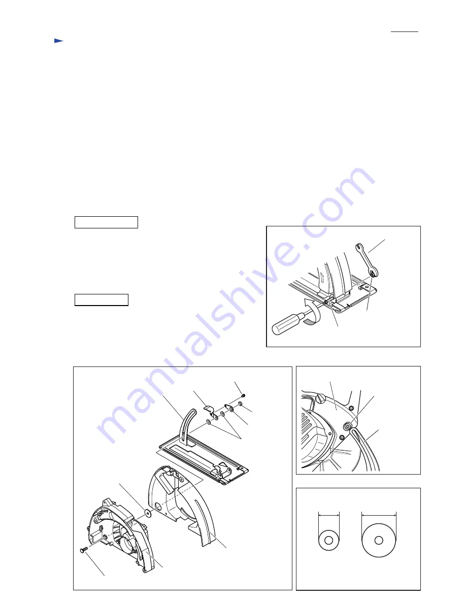
Fig. 1

Fig. 2

Fig. 3

Fig. 4

Wrench 8

[2] LUBRICATION

[1] NECESSARY REPAIRING TOOLS

Retaining ring pliers ST-2N (1R003) .................... For removal/installation of Safety cover

Bearing setting pipe 16-8.2 (1R026) ..................... For removing Gear

Ring 22 (1R217) .................................................... For removing Gear

Bearing extractor (1R263) ..................................... For removing Bearing box

Bearing extractor (1R269) ..................................... For removing Ball bearing

Retaining ring S and R pliers (1R291) ................... For removal/installation of the Retaining ring on Spindle

Wrench for bearing retainer (1R316) ..................... For removal/installation of Bearing retainer

Put 8g of Makita grease N No.1 in the gear room of Gear housing complete.

[3] DUSASSEMBLING AND ASSEMBLING

CAUTION: Be sure that the tool is switched off and unplugged before starting disassembling/assembling.
CAUTION: When using a blower for cleaning, always wear safety goggle to protect your eyes from metal dust.

[3] -1. Replacement of Base

DISASSEMBLING

1) Remove (+) Pan head screw M5 from the hinge portion of

    Base while holding Hex lock nut M5-8 with wrench 8 or the

    like so that it cannot turn together with the screw. (

Fig. 1

)

2) Release depth adjustment lock, and then remove Pan head

    screw M4x8. Now Lock plate can be removed from the depth

    guide of Base.   Remove Hex nut M6, and now Lock lever 

    section can be disassembled as illustrated in 

Fig. 2

.

Always follow the instructions of the SAFETY RULES and OPERATING INSTRUCTIONS described in the
instruction manual.

(+) Pan head screw M5

Hex lock nut M5-8

Lever plate

Gear housing (blade case)

Flat washer 6

(253804-1)

Lock plate

Hex nut M6

Pan head screw M4x8

Flat washer 6

(253783-3)

Depth guide

Cap square neck bolt M6x20

ASSEMBLING

Do not forget to put Flat washer 6 (Part No.253783-3) between

Gear housing (blade case) and the depth guide of Base. (

Fig. 3

)

Be careful not to place Flat washer 6 (Part No.253804-1) there.

The two Flat washers can be easily distinguished by outer

diameter as illustrated in 

Fig. 4

.

Flat washer 6

(253783-3)

Depth guide

Gear housing cover

Gear housing cover

Flat washer 6

(253804-1)

15mm

Flat washer 6

(253783-3)

25mm

Summary of Contents for 4131

Page 1: ...nvenient for plunge cutting Assorted TCT Saw blade Guide rule 4131 Metal Cutter 185mm 7 1 4 Specification Note The standard equipment for the tool shown may differ from country to country Dimensions mm Width W Height H Length L 358 14 1 8 273 10 3 4 280 11 Standard equipment Cermet tip saw 185mm 7 1 4 1 pc Hex wrench 1 pc Wrench holder Safety goggle 1 pc No load speed rpm min 1 Power input W Rated...

Page 2: ...rew M5 from the hinge portion of Base while holding Hex lock nut M5 8 with wrench 8 or the like so that it cannot turn together with the screw Fig 1 2 Release depth adjustment lock and then remove Pan head screw M4x8 Now Lock plate can be removed from the depth guide of Base Remove Hex nut M6 and now Lock lever section can be disassembled as illustrated in Fig 2 Always follow the instructions of t...

Page 3: ...x and Gear Housing Blade Case 1 Remove Retaining ring on Safety cover using Retaining ring pliers ST 2N 1R003 At this time hold the ring with gloved hand so that it cannot fly off 2 By removing Safety cover three parts can be disassembled in the following order Washer 42 Spacer Thickness ring See Fig 7 Remember this order for reassembling 3 If Safety cover does not move smooth remove metal dust fr...

Page 4: ...er left handed by turning clockwise using Wrench for bearing retainer 1R319 Fig 11 5 Place Bearing box on Ring 22 1R217 and put Bearing setting pipe 16 8 2 1R026 on the gear installation end of Spindle Press Spindle out using arbor press to remove Helical gear 48 and Ball bearing 6202DDW Fig 12 3 6 Replacement of Switch and Power Supply Cord Note Switch and Power supply cord can be replaced withou...

Page 5: ...asten Gear housing blade case to Base so that cutting depth can be adjusted smoothly without wobbling Refer to 1 Replacement of Base and Fig 1 on page 2 4 2 Lever Plate of Cutting Depth Lock Lever Fix Lock plate to Lock lever so that the line through Cap square neck bolt M6x20 and Pan head screw M4x8 forms an angle of approximately 10 to 30 degrees to the horizontal axis when the lever is locked F...

Page 6: ...iagram Switch Noise suppressor Support complete Note Some countries do not use Noise suppressor Power supply cord Hold the lead wires from Support complete with this lead wire holder Route the lead wires from Support complete through this through hole when installing Baffle plate Motor housing portion Baffle plate portion through opening Baffle plate Two lead wires black from Support complete ...

Page 7: ... Fig 16 3 In Handle Route as illustrated in Fig 17 Fig 16 Fig 17 Wiring diagram Two lead wires black from Support complete Sponge ring Two lead wires black from Support complete Put the lead wires through Sponge ring and hold them with lead wire holders Noise suppressor not used for some countries ...

Reviews: