Menu/
INSTRUCTION
C: Commands
A: Activities
Submenu
DVOR 432
Installation
Operation and Maintenance
4-24
Ed. 01.04
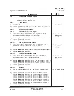
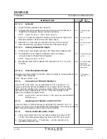
4.11.2.3
Azimuth
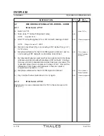
a) Check azimuth indication: 'M1 Azimuth'
b) Change azimuth for desired value according to announcement of
A/FC
T1 Azimuth Align-
Flight Check Engineer. Record azimuth indication.
ment ---,- °
NOTE:
Range of values: 0...359.9. Note new value.
c) Add 1.0° to azimuth indication and key in this value as upper limit.
A/AL1
M1 Azimuth Upper
(Recommendation: Perform this after flight check)
Limit ---,- °
d) Subtract 1.0° fromazimuth indication and key in this value as
A/AL1
M1 Azimuth Lower
lower limit
(Recommendation: Perform this after flight check)
.
Limit ---,- °
4.11.2.4
Identity Modulation Depth
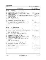
a) Check Ident. mod depth indication: 'M1 Mod. Depth Identity AM'
b) Change Ident. mod. depth for desired value according to
A/FC
T1 Mod. Depth Iden-
announcement of Flight Check Engineer.
tity AM --,- %
NOTE:
Range of values: 0...20.0.
c) Recalibrate 'Mod. Depth Identity AM' indication for 10 % for both
A/MC
M1 Calibrate Mod.
monitors.
Depth Ident.
M2 Calibrate Mod.
Depth Ident.
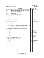
4.11.2.5
Voice Modulation Depth
Change voice mod. depth for desired value according to announcement
A/FC
T1 Mod. Depth
of Flight Check Engineer.
Voice AM --,- %
NOTE: Range of values: 0...40.
4.11.3
Correction of TX2 with Monitor 2
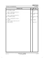
Correct TX2 in the same way as described for TX1 in section 4.11.1,
A/FC
however set the 30 Hz AM and 9960 Hz mod. depth, 30 Hz FM mod.
index, azimuth, identity and voice mod. depth of TX2 in order to obtain
the same monitor indications as for TX1. Later, the settings of TX2
have to be confirmed by flight check.
NOTE:
Switch off TX1 and then Switch on TX2. Verify that both MONITOR
BYPASS are on.
4.11.4
Adjustment of Monitor 2 with TX1/TX2
Correct monitor 2 in the same way as described for monitor1 in 4.11.2
A/MC
and 4.11.3, but do not change transmitter adjustments. Use activity mask
A/AL2
A/MC 'Monitor Calibration' and A/AL2 'AlarmLimits M2'.
4.11.5
Check of Monitor Alarm Limits
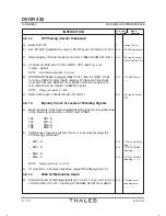
a) The monitor alarm limits can be checked either by means of TX1
or TX2. The following describes this check with TX1 as main TX.
b) Change of alarmlimits - if necessary - can be carried out as
described in Section 4.8.
Summary of Contents for DVOR 432
Page 2: ......
Page 4: ......
Page 16: ...DVOR 432 Table of Contents Operation and Maintenance X Ed 01 04 ...
Page 38: ...DVOR 432 General Information Operation and Maintenance 1 6 Ed 01 04 ...
Page 40: ...DVOR 432 General Information Operation and Maintenance 1 8 Ed 01 04 ...
Page 46: ......
Page 66: ...DVOR 432 Installation Operation and Maintenance 2 24 Ed 01 04 ...
Page 74: ......
Page 136: ...DVOR 432 Installation Operation and Maintenance 4 32 Ed 01 04 ...
Page 172: ...DVOR 432 Repairs Operation and Maintenance 6 22 Ed 01 04 ...
Page 186: ...DVOR 432 Repairs Operation and Maintenance 6 36 Ed 01 04 ...
Page 192: ...DVOR 432 Installation Operation and Maintenance Annex Nextfield AN 4 Ed 01 04 ...
Page 194: ......
Page 196: ...DVOR 432 General Operation and Maintenance Annex Nextfield L 2 Ed 01 04 ...
Page 204: ...DVOR 432 Alignment Procedure Operation and Maintenance Annex Nextfield AN 14 Ed 01 04 ...
Page 234: ...DVOR 432 Maintenance Operation and Maintenance Annex Nextfield AN 44 Ed 01 04 ...

