DVOR 432
Maintenance
Operation and Maintenance
5-6
Ed. 01.04
The internal temperature in the battery compartment is subject to fluctuations dependent on the time
of day and time of year. The considerable mass of the batteries and the associated high thermal inertia
mean that temperature fluctuations dependent on the time of day are insignificant and can be ignored.
It is necessary on the other hand to determine the average temperature in the battery compartment
during the hot and cold seasons or to estimate it on the basis of experience. The optimum charging
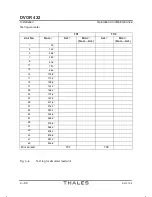
voltage can be read off fromthe table when the average temperature has been calculated.
It is not necessary in moderate climatic zones to take seasonal fluctuations into account. If the batterĆ
ies are accommodated inside a shelter or a building, the fluctuations between summer and winter are
not very great, and the mean temperature will not deviate substantially from 20 °C. In such cases it
is not necessary to optimize the trickle charge voltage as described here. This only becomes necesĆ
sary if the batteries are installed outside the shelter or in hot or cold zones without an air-conditioned
battery compartment.
If the mean annual temperature is known during the installation phase, adjustments can be carried
out by the Thales ATM installation team. Otherwise they should be carried out by the customer's own
maintenance personnel as follows.
5.3.3.2
Matching the Voltage
NOTE:
This procedure is performed once during installation or if other battery types are used.
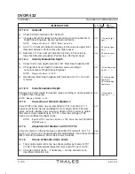
The battery must be connected. Switch off the transmitters. Using the switches on the front panel
switch off the ACC units except the outer left one, which has to be adjusted first. Beginning with left
ACC unit adjust the ACC units as follows:
- Connect a digital voltmeter to the test jacks on the front panel of the switched-on ACC unit.
- Set the desired voltage carefully at the potentiometer on the front panel with the aid of a calibration
screwdriver. It should be possible to obtain the value specified in the table in 5.3.3.1 to within a
tolerance of ±0.2 V.
- Switch off the adjusted ACC unit.
- Switch on the next ACC unit and adjust it in the same way.
- Adjust all installed ACC units in the same way.
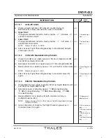
When all units have been set in this way measurements should be performed as follows:
- Disconnect the battery.
- Perform measurements bBAT and -BAT on the BCPS terminal plate using a digital
voltmeter:
First measurement
:
Transmitter off, BCPS without load
Second measurement :
Transmitter on, BCPS with load
The values should not deviate fromthe set value by more than ±1 %. If the deviation is greater, the
relevant module can be determined by deactivating the power units individually and observing the
voltage change. The voltage of this unit must then be corrected upwards or downwards. The BCPS
is then ready for service.
Summary of Contents for DVOR 432
Page 2: ......
Page 4: ......
Page 16: ...DVOR 432 Table of Contents Operation and Maintenance X Ed 01 04 ...
Page 38: ...DVOR 432 General Information Operation and Maintenance 1 6 Ed 01 04 ...
Page 40: ...DVOR 432 General Information Operation and Maintenance 1 8 Ed 01 04 ...
Page 46: ......
Page 66: ...DVOR 432 Installation Operation and Maintenance 2 24 Ed 01 04 ...
Page 74: ......
Page 136: ...DVOR 432 Installation Operation and Maintenance 4 32 Ed 01 04 ...
Page 172: ...DVOR 432 Repairs Operation and Maintenance 6 22 Ed 01 04 ...
Page 186: ...DVOR 432 Repairs Operation and Maintenance 6 36 Ed 01 04 ...
Page 192: ...DVOR 432 Installation Operation and Maintenance Annex Nextfield AN 4 Ed 01 04 ...
Page 194: ......
Page 196: ...DVOR 432 General Operation and Maintenance Annex Nextfield L 2 Ed 01 04 ...
Page 204: ...DVOR 432 Alignment Procedure Operation and Maintenance Annex Nextfield AN 14 Ed 01 04 ...
Page 234: ...DVOR 432 Maintenance Operation and Maintenance Annex Nextfield AN 44 Ed 01 04 ...

