DVOR 432
Operation and Maintenance
Fault Location
6-5
Ed. 01.04
Step
Fault (4 cont.)
A
B
C
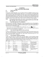
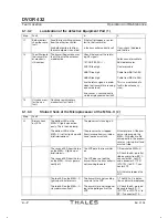
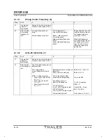
4.3.3
The modulation depth of the
identity is wrong and, indeĆ
pendently of the transmitted
power, the control signal is
wrong.
Re-check under 'TX1/2 BITE
ADC-2':
ID_ST_2 and ID_ST_5
If these signals are not
good, replace MSG-S or
MSG-C.
4.3.4
Ident Morse code is not workĆ
ing or is defective.
Is the code correctly set?
The Morse code is generated
completely on the MSG-C.
Replace MSG-C
6.1.3.6
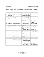
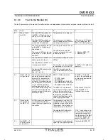
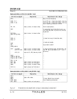
Modulation by Sidebands too low or wrong (5)
Thisdescriptionconcernssignalsthatarecomposedofcarrier(CSB)andsidebandsignals(SBO).Here,notonlytherightlevel
conditionsof CSB and SBO must be ensured, but also the right phase. Errors of the sidebands almost always lead to azimuth
errors.Both error types must be considered in relation to one another.
Step
Fault
A
B
C
5.1
One monitor
good, one
monitor bad
Search for the fault in the bad
monitor and continue with 8.1.
Condition: neither monitor may
have more than 110 % RF
level; otherwise, measuring erĆ
rors may occur.
5.2
Bothmonitors
show the same
fault.
Search for the fault in the
transmitter.
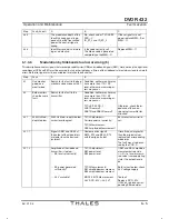
Condition: neither monitor may
have more than 110 % RF
level; otherwise, measuring erĆ
rors may occur.
TX1/2 BITE ADC-1:
ACA1R normal?
ASB1R and ASB2R normal?
Otherwise, check the imĆ
pedance at the correĆ
sponding transmitter terĆ
mination.
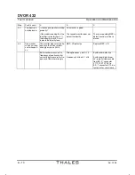
5.2.1
9960 Hz Mod.-
depth too low
9960 Hz Mod.-depth too low,
carrier level too great
TX1/2 Adjustments:
Carrier power set correctly?
TX1/2Measurement:
CSB Amplitude Measurement?
Ensure correct carrier leĆ
vel.
5.2.1.1
Signals ASB1 and ASB2 at
the output of the modulators
are lower than the basic adĆ
justment.
Compare drive signals
SB1A_ST3 and SB2A_ST3
with the original values.
If results equal or greater
than the original values,
replacethecorresponding
modulator.
The fault may also be cauĆ
sed by the CCP-D.
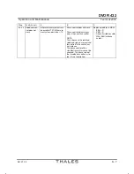
5.2.1.2
Amplitude of the sideband
transmitter is too low:
- SB level set correctly?
- SB power generated
sufficiently?
- 28 V available?
TX1/2 Adjustments:
SB1 power level,
SB2 power level
TX1/2 Measurements:
SB1 amplitude measurement,
SB2 amplitude measurement
MON1/2 BITE Measurement:
28 V DCC-MV > 26.5 V?
If SB1 and SB2 amplitude
measurementsdeviate
<±5 % to former measuĆ
red value (same operating
state), the output level is
ok.
Both values too low, check
28 V voltage supply.
Too low?
Replace DCC-MV.
If 28 V ok, replace corresĆ
ponding SB modulator.
Summary of Contents for DVOR 432
Page 2: ......
Page 4: ......
Page 16: ...DVOR 432 Table of Contents Operation and Maintenance X Ed 01 04 ...
Page 38: ...DVOR 432 General Information Operation and Maintenance 1 6 Ed 01 04 ...
Page 40: ...DVOR 432 General Information Operation and Maintenance 1 8 Ed 01 04 ...
Page 46: ......
Page 66: ...DVOR 432 Installation Operation and Maintenance 2 24 Ed 01 04 ...
Page 74: ......
Page 136: ...DVOR 432 Installation Operation and Maintenance 4 32 Ed 01 04 ...
Page 172: ...DVOR 432 Repairs Operation and Maintenance 6 22 Ed 01 04 ...
Page 186: ...DVOR 432 Repairs Operation and Maintenance 6 36 Ed 01 04 ...
Page 192: ...DVOR 432 Installation Operation and Maintenance Annex Nextfield AN 4 Ed 01 04 ...
Page 194: ......
Page 196: ...DVOR 432 General Operation and Maintenance Annex Nextfield L 2 Ed 01 04 ...
Page 204: ...DVOR 432 Alignment Procedure Operation and Maintenance Annex Nextfield AN 14 Ed 01 04 ...
Page 234: ...DVOR 432 Maintenance Operation and Maintenance Annex Nextfield AN 44 Ed 01 04 ...

