DVOR 432
Operation and Maintenance
Repairs
6-13
Ed. 01.04
6.2
REPAIRS
6.2.1
General
The repair activities are designed to restore the ready condition of a faulty systemin the shortest
possible time. The system is repaired by replacing the defective subassembly. The defective subasĆ
semblies can then be sent to the manufacturer for repair.
NOTE:
Subassemblies and components which are sent to the manufacturer for repair or returns
must be packed in a way that no damage of the parts could arise. It is recommended to
use the original packing, e.g. of the spare part, or a comparable packing in corresponding
performance to ensure a safe shipping of defective subassemblies or components.
Handling of subassemblies with electrostatically sensitive components see section
6.2.1.1.3 .
6.2.1.1
Safety precautions
6.2.1.1.1
General regulations
The safety regulations laid down by the local authorities (e.g. concerning accident prevention, work
safety or operation of electronic equipment and navigation systems) must be observed at all times.
The purpose of safety precautions is to protect persons and property, and they must always be heedĆ
ed. See also Part 1, Section 1.4.
Work should not be carried out outside the shelter or on the antenna systemduring a storm, due to
the danger of injury by lightning.
Station shutdown due to repair and maintenance: The responsible authorities must be notified of any
work which may require operation of the system to be interrupted, in accordance with national regulaĆ
tions.
6.2.1.1.2
Work on the equipment
WARNING
In order to avoid risks to persons and consequential damage to subassemblies, the releĆ
vant transmitter must be switched off. The battery-charged power supply (BCPS) must
always be disconnected from the mains before any work, other than measuring the voltĆ
age is carried out on it. RF cables must not be bent to a radius of less than 50 mm.
Use switch TX1 or TX2 prior to removing or inserting a subassembly or prior to removing a plug-in
connector during the course of repair and maintenance activities (see Section 6.2.3.1 for exceptions).
Switches TX1 and TX2 deactivate the DC converters for the transmitter 1 and transmitter 2 subassemĆ
blies respectively. The subassemblies which are common to both transmitters are exceptions: they
cannot be switched on and off with either TX1 or TX2. Switch NAV deactivates the complete equipĆ
ment.
6.2.1.1.3
Handling Electrostatically Sensitive Subassemblies
The ILS and (D)VOR installations contain subassemblies (plug-in cards) equipped with components
which are sensitive to electrostatic discharge. When replacing subassemblies and plug-in cards
containing electrostatically sensitive components, special precautionary measures should be taken
during removal, transport and installation in order to prevent damage to the components. We refer
to the customer documentation of the manufacturer.
Subassemblies which contain electrostatically sensitive components are
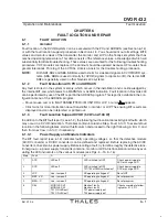
marked with this symbol.
Summary of Contents for DVOR 432
Page 2: ......
Page 4: ......
Page 16: ...DVOR 432 Table of Contents Operation and Maintenance X Ed 01 04 ...
Page 38: ...DVOR 432 General Information Operation and Maintenance 1 6 Ed 01 04 ...
Page 40: ...DVOR 432 General Information Operation and Maintenance 1 8 Ed 01 04 ...
Page 46: ......
Page 66: ...DVOR 432 Installation Operation and Maintenance 2 24 Ed 01 04 ...
Page 74: ......
Page 136: ...DVOR 432 Installation Operation and Maintenance 4 32 Ed 01 04 ...
Page 172: ...DVOR 432 Repairs Operation and Maintenance 6 22 Ed 01 04 ...
Page 186: ...DVOR 432 Repairs Operation and Maintenance 6 36 Ed 01 04 ...
Page 192: ...DVOR 432 Installation Operation and Maintenance Annex Nextfield AN 4 Ed 01 04 ...
Page 194: ......
Page 196: ...DVOR 432 General Operation and Maintenance Annex Nextfield L 2 Ed 01 04 ...
Page 204: ...DVOR 432 Alignment Procedure Operation and Maintenance Annex Nextfield AN 14 Ed 01 04 ...
Page 234: ...DVOR 432 Maintenance Operation and Maintenance Annex Nextfield AN 44 Ed 01 04 ...


