DVOR 432
Repairs
Operation and Maintenance
6-20
Ed. 01.04
6.2.3.2.3
Replace and Reconfigure Subassembly LCP
Before starting any replacement it is recommend to read out all parameters of the installation: Use
command
Download Parameters
or make a printout of all parameters or write down manually the indiĆ
cated parameters if other measures are not possible. It is also recommended to generate a copy of
the specific site files as backup:
- Click the
control
button in the main status window in the PC User Program.
- Select
File Transfer
and
Copy site file to PC
in the submenu.
- Copy all files with the extension:
*.sit
,
*.oio
,
*.msk
,
*.ptt.
The LCP subassembly contains routines which allow to check the LCP hardware and to configure
the LCP to the systemILS 420 or CVOR/DVOR.
The spare subassembly LCP is not configured to a specific subsystem (i.e. ILS 420 or CVOR/DVOR).
This is to be done restarting the subsystemwith power on:
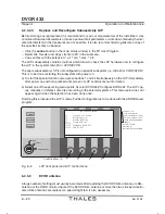
a) To start the special function menu press buttons 1 and 4 simultaneously on the LCP immediately
after power on and hold pressed until screen of LCP contains menu information.
b) Select one of the upcoming menu points, here for DVOR 432:
Configure DVOR 432.
The LCP copĆ
ies, renames or deletes some files according to the selected systems. This menu point does not
appear again when the selection has been done once.
Finishing this procedure the LCP is ready. Further configuration is to be done with the ADRACS user
program.
REMOTE
LOCAL
MAINTENANCE
ALARM
WARNING
NORMAL
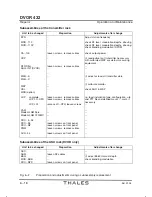
LCP Control Menu
S1
Test the LCP board
S2
Delete drive d:
S3
Restore REU.exe
S4
Secure REU.exe
S1+S2
S1+S3 Configure DVOR 432
S1+S2 Exit to DOS
control buttons (S)
1
4
2
3
used for factory test
used to delete bad or wrong
.sit-files on drive d: of LCP
saving reu.exe update REU
not used in CVOR
select LCP use
Exit control menu to standard
Factory use only:
firmware
Fig. 6-3
LCP front panel and LCP control menu
6.2.3.3
DVOR antenna
A large number of settings must usually be remade after replacing the DVOR CSB-antenna or a SB-
antenna or the DVOR monitor dipole. If the DVOR CSB-antenna or more then two side by side alloĆ
cated SB-antennas are replaced, a special flight test is also necessary.
Summary of Contents for DVOR 432
Page 2: ......
Page 4: ......
Page 16: ...DVOR 432 Table of Contents Operation and Maintenance X Ed 01 04 ...
Page 38: ...DVOR 432 General Information Operation and Maintenance 1 6 Ed 01 04 ...
Page 40: ...DVOR 432 General Information Operation and Maintenance 1 8 Ed 01 04 ...
Page 46: ......
Page 66: ...DVOR 432 Installation Operation and Maintenance 2 24 Ed 01 04 ...
Page 74: ......
Page 136: ...DVOR 432 Installation Operation and Maintenance 4 32 Ed 01 04 ...
Page 172: ...DVOR 432 Repairs Operation and Maintenance 6 22 Ed 01 04 ...
Page 186: ...DVOR 432 Repairs Operation and Maintenance 6 36 Ed 01 04 ...
Page 192: ...DVOR 432 Installation Operation and Maintenance Annex Nextfield AN 4 Ed 01 04 ...
Page 194: ......
Page 196: ...DVOR 432 General Operation and Maintenance Annex Nextfield L 2 Ed 01 04 ...
Page 204: ...DVOR 432 Alignment Procedure Operation and Maintenance Annex Nextfield AN 14 Ed 01 04 ...
Page 234: ...DVOR 432 Maintenance Operation and Maintenance Annex Nextfield AN 44 Ed 01 04 ...


