DVOR 432
Operation and Maintenance
Installation
Annex Nextfield
AN-1
Ed. 01.04
CHAPTER 1
INSTALLATION AND ALIGNMENT PROCEDURE
This Annex describes the installation of the DVOR nextfield dipoles and the settings for the nextfield
monitoring during first alignment of the DVOR installation.
1.1
PREREQUISITES
The DVOR antenna system is completely installed.
WARNING
Sturdy shoes, safety gloves and safety helmets must be worn during installation. Safety
belts with rescue line and swivel snaphookshould be used when working on the counterĆ
poise platform.
1.2
INSTALLATION OF NEXTFIELD DIPOLES
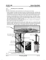
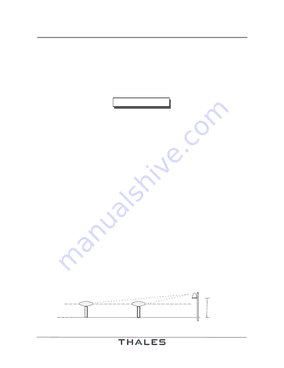
See Fig. 1-1, 1-2.
To install the nextfield dipoles on the counterpoise the following parts are required.
- GFK mast tube (approx. 3 m length)
- 2 clamps with nuts and screws
- Nextfield dipole with clamping band fastening
- Monitor cable
- Cable conduit with fastenings
- Cable ties, UV resistant
The nextfield dipoles are installed as far as possible at the counterpoise edge. The nextfield dipoles
are fixed each on a GFK mast tube, which is mounted with clamps at the outer supports of the counterĆ
poise.
NOTE:
The distance between middle antenna and the nextfield dipoles must not fall below 11 m.
Favorable are values between 12.5 and 17 m. If several dipoles are installed, the dipoles
must have the same distance each ±0,2 m to the middle antenna, because all monitor
inputs use the same gain control (AGC).
The signal quality depends not only on the installation site of the antenna, but also on the
transmitting frequency. Therefore the signals which are processed in the monitor have to
be checked during adjustment. In this way bad signals due to an unfavorable antenna
location may be noticed. As far as good signals are obtained, it may be varied from the
above mentioned antenna position.
The azimuth position of the nextfield dipole (or several dipoles) is optionally selectable. The user can
determine with the project engineer, where a nextfield dipole shall stand. The alarm limits are set acĆ
cording to this position on the PC. Practically special angle ranges, e.g. the approach direction, are
preferred monitored. The mounting position shall be oriented due to the fastening possibilities on the
outer supports of the counterpoise.
A51
A1
1800 mm
Counterpoise
middle antenna
sideband antenna
nextfield dipole
Fig. 1-1
Height position of nextfield dipole
Summary of Contents for DVOR 432
Page 2: ......
Page 4: ......
Page 16: ...DVOR 432 Table of Contents Operation and Maintenance X Ed 01 04 ...
Page 38: ...DVOR 432 General Information Operation and Maintenance 1 6 Ed 01 04 ...
Page 40: ...DVOR 432 General Information Operation and Maintenance 1 8 Ed 01 04 ...
Page 46: ......
Page 66: ...DVOR 432 Installation Operation and Maintenance 2 24 Ed 01 04 ...
Page 74: ......
Page 136: ...DVOR 432 Installation Operation and Maintenance 4 32 Ed 01 04 ...
Page 172: ...DVOR 432 Repairs Operation and Maintenance 6 22 Ed 01 04 ...
Page 186: ...DVOR 432 Repairs Operation and Maintenance 6 36 Ed 01 04 ...
Page 192: ...DVOR 432 Installation Operation and Maintenance Annex Nextfield AN 4 Ed 01 04 ...
Page 194: ......
Page 196: ...DVOR 432 General Operation and Maintenance Annex Nextfield L 2 Ed 01 04 ...
Page 204: ...DVOR 432 Alignment Procedure Operation and Maintenance Annex Nextfield AN 14 Ed 01 04 ...
Page 234: ...DVOR 432 Maintenance Operation and Maintenance Annex Nextfield AN 44 Ed 01 04 ...


