Menu/
INSTRUCTION
C: Commands
A: Activities
Submenu
DVOR 432
Alignment Procedure
Operation and Maintenance
Annex Nextfield
AN-16
Ed. 01.04
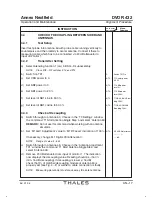
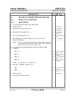
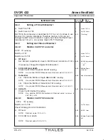
4.3.2
Test Setup (recommended)
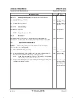
Disconnect matcher/decoupling module from antenna1 and arrange test
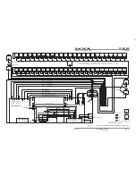
setup according to Fig. 4-4. Connect measuring cable via 20 dB
attenuator to FORWARD-output of directional coupler.
NOTE: Other test setups are possible. It depends on the measuring device capaĆ
bilities of the customer.
4.3.3
Transmitter Setting
a) Switch on TX1.
C
Switch TX1 On
b) Set carrier power to 10 W.
A/TS
T1 Carrier power
10 W
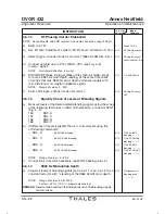
c) Set SB1 power to 0.
A/TS
T1 SBA power
level 0%
d) Set SB2 power to 0.
T1 SBB power
level 0%
e) Switch off antenna rotation. The sideband antennas are switched to
50
W
termination.
Click'ON/OFF' icon and select with
change destination
and
change group
the 'ASU Test Commands' and then 'ASU test
no SB radiation'; click'program TX-1'.
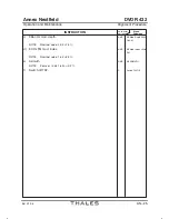
4.3.4
Matching Procedure
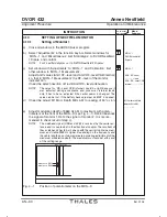
a) Set 'M1 AGC Adjustment' value to 'M1 RF Level' indication of 100 %.
A/TS
M1 AGC Adjustment
--,- %
If necessary, change 'M1 Digital.Ctrl.Attenuation'.
-- dB
NOTE:
Range of values: 2...255
b) Connect measuring cable to reflected output of directional coupler
at antenna1 and remove 20 dB attenuator at input of monitor 1.
NOTE:
See test setup Fig. 4-4.
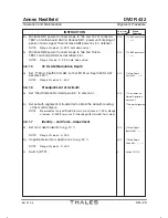
c) Set 'M1 RF Level' indication to a minimum by alternately adjusting
both plate capacitors C
A
(both in the same direction) and C
Tr
of
antenna1.
REMARK:
For this measurement the antenna cover must be put on proĆ
visionally and measuring personnel must have moved away
about 7 m from the antenna under test.
NOTE:
Nominal value: less then 5 % (min. 26 dB matching).
d) Connect test setup to antenna 2. Reconnect matcher/decoupling
module to antenna 1 normally. Match antenna 2 and then all other
antennas including the center antenna in the same way.
e) After all antennas are measured, repeat procedure and check
antennas 1 to 50 again. If need be readjust.
f)
Reconnect center antenna normally and remove test setup.
g) Switch off TX1.
C
Switch TX1 Off
Summary of Contents for DVOR 432
Page 2: ......
Page 4: ......
Page 16: ...DVOR 432 Table of Contents Operation and Maintenance X Ed 01 04 ...
Page 38: ...DVOR 432 General Information Operation and Maintenance 1 6 Ed 01 04 ...
Page 40: ...DVOR 432 General Information Operation and Maintenance 1 8 Ed 01 04 ...
Page 46: ......
Page 66: ...DVOR 432 Installation Operation and Maintenance 2 24 Ed 01 04 ...
Page 74: ......
Page 136: ...DVOR 432 Installation Operation and Maintenance 4 32 Ed 01 04 ...
Page 172: ...DVOR 432 Repairs Operation and Maintenance 6 22 Ed 01 04 ...
Page 186: ...DVOR 432 Repairs Operation and Maintenance 6 36 Ed 01 04 ...
Page 192: ...DVOR 432 Installation Operation and Maintenance Annex Nextfield AN 4 Ed 01 04 ...
Page 194: ......
Page 196: ...DVOR 432 General Operation and Maintenance Annex Nextfield L 2 Ed 01 04 ...
Page 204: ...DVOR 432 Alignment Procedure Operation and Maintenance Annex Nextfield AN 14 Ed 01 04 ...
Page 234: ...DVOR 432 Maintenance Operation and Maintenance Annex Nextfield AN 44 Ed 01 04 ...


