3-4
User Manual PN 84469 Rev L
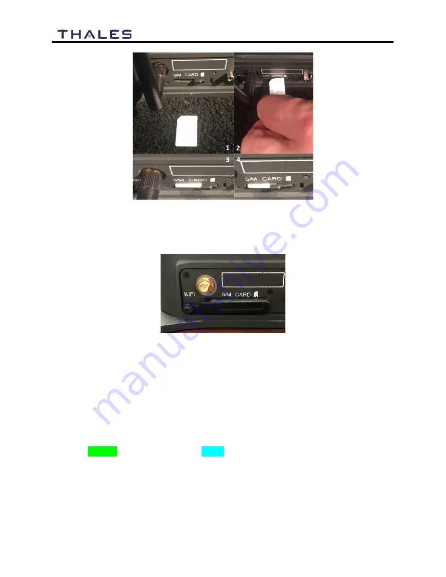
Figure 3-4 Installing SIM Card and Engaging the Lock
4.
Secure the SIM Card cover once the SIM Card has been locked into place to prevent
moisture or dust intrusion. (Figure 3-5)
Figure 3-5 Secure the SIM Card Cover
STEP 4: Power the VesseLINK
™
Unit.
Before powering the unit, make sure the DC power cable is connected to a 10-32VDC source,
the polarity is correct, and the DC cable is securely connected to the BDU. If using the AC/DC
power supply, connect one end to the BDU’s 12V DC input and connect the power cord to a
120V or 240V AC outlet. The antenna must also be connected per the system installation
manual. Power the unit by pressing and releasing the power button on the BDU (Figure 3-1).
NOTE: After the button is pressed and released, a few seconds pass before the System LED (left)
starts flashing. It may take a few minutes on initial startup for all three LED’s on the unit top to
turn solid GREEN (middle LED may turn BLUE). You may see an occasional red LED during
power up. This is normal. Refer to Table 3-2 for more information on the status LEDs.
Summary of Contents for VesseLINK Certus 200
Page 12: ...xii Uer Manual PN 84469 Rev L ...
Page 13: ...xiii Uer Manual PN 84469 Rev L ...
Page 15: ...xv Uer Manual PN 84469 Rev L ...
Page 16: ...xvi Uer Manual PN 84469 Rev L ...
Page 17: ...xvii Uer Manual PN 84469 Rev L ...
Page 18: ...xviii Uer Manual PN 84469 Rev L ...
Page 28: ...2 8 User Manual PN 84469 Rev L THIS PAGE INTENTIONALLY LEFT BLANK ...
Page 58: ...4 22 User Manual PN 84469 Rev L Figure 4 25 Settings Wi Fi Screen ...
Page 62: ...4 26 User Manual PN 84469 Rev L Figure 4 26 Settings LAN Screen ...
Page 65: ...4 29 User Manual PN 84469 Rev L Figure 4 27 Settings WAN Screen ...
Page 68: ...4 32 User Manual PN 84469 Rev L Figure 4 28 Settings Phone Screen ...
Page 78: ...4 42 User Manual PN 84469 Rev L Figure 4 35 Settings Radio Gateway ...
Page 84: ...4 48 User Manual PN 84469 Rev L Figure 4 37 Settings Secondary Data Flows ...


