background image

Owner’s Manual

9

Owner’s Manual

8

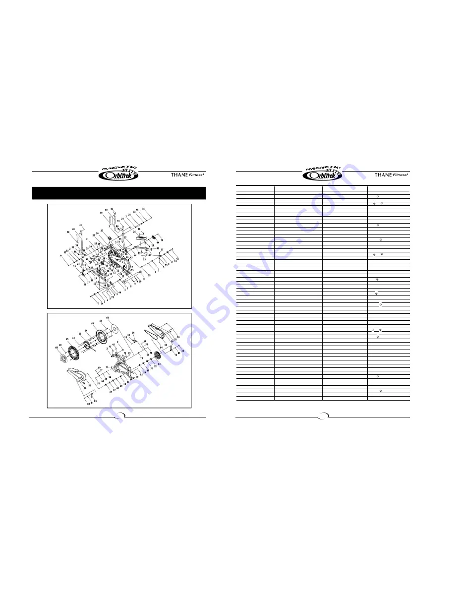
NO.

NAME

QUANTITY

SPEC

1

LEFT HINGE BOLT

1

1/2"

2

BUSHING I 

10

28*16

3

LOCK NUT

4

M10

4

STEEL BUSHING 

4

28*   14*10

5

CONNECTING TUBE

2

6

SPRING WASHER 

2

1/2"

7

LEFT LOCK NUT 

1

8

ADJUSTABLE END CAP 

2

9

CARRIAGE BOLT

4

M8*60

10 

REAR STABILIZER 

1

50*1.5

11 

ARC WASHER 

4

12 

DOMED NUT 

4

M8

13 

LOCK NUT 

5

M8

14 

FLAT WASHER 

4

8

15 

HEX HEAD BOLT

4

M10*55

16 

SCREW 

6

ST4.2*19

17 

LEFT HANDLEBAR COVER(L) 

1

18 

BUSHING2 

4

18*   10*10

19 

PEDAL TUBE 

2

20 

HEX HEAD BOLT

4

M8*50

21

LEFT HANDLEBAR COVER(R) 

1

22 

RIGHT HANDLEBAR 

1

23

FRONT STABILIZER 

1

24 

LEFT CONNECTING TUBE 

1

25 

FRONT END CAP 

2

50*1.5

26 

RIGHT PEDAL 

1

27 

LEFT PEDAL 

1

28 

HEX HEAD BOLT

2

M6*45

29 

WHEEL 

2

22*30.5

30 

LOCK NUT 

2

M6

31 

HINGE SCREW 

2

3/8"*20

32 

SPRING WASHER 

2

10

33 

D SHAPER WASHER 

2

34 

LOCKING KNOB 

2

35 

PLASTIC SLEEVE

2

36 

MAIN FRAME 

1

37 

COMPUTER 

1

38 

SPRING BAR 

1

39 

FOAM GRIP 

2

33*    23*310

40 

LEFT HANDLEBAR 

1

41 

HANDLEBAR END CAP 

2

25.4*2

42 

RIGHT HINGE BOLT

1

1/2"

43 

RIGHT HANDLEBAR COVER(L) 

1

44 

RIGHT HANDLEBAR COVER(R) 

1

45 

PLASTIC SLEEVE 

2

46 

END CAP 

2

30*30*1.5

47 

FIXING WASHER(L) 

1

48 

WASHER 

1

49 

COLLAR BALL 

2

50 

COLLAR HOUSING

2

51

FIXING WASHER(R) 

1

52 

WASHER 

1

40*2.8

53 

STRAP WHEEL 

1

54 

STRAP-FIXER PLATE

1

55 

RIGHT CONNECTING TUBE 

1

56 

FLAT WASHER 

2

5

57

LEFT CHAIN COVER 

1

58 

FIXING NUT 

2

M10*1.0

EXPLODED VIEW & PARTS LIST

Summary of Contents for Magnetic Elite Orbitrek

Page 1: ...nefitness com Making Fitness Fun OWNER S MANUAL IMPORTANT Please read all instructions carefully before using this product Retain this manual for future reference 9 02 Safety Notice 2 Assembly Usage 3...

Page 2: ...ng at a time 13 Do not use abrasive cleaning articles to clean the machine Remove drops of sweat from the machine immediately after finishing training 14 Always wear appropriate workout clothing when...

Page 3: ...s using the Hinge Screws No 31 2 D Shaped Washers No 33 2 Spring Washers No 32 2 Hinge Screws No 31 Insert the Right Hinge Bolt No 42 with Arc Washer No 74 through the Connecting Tube No 5 and screw i...

Page 4: ...ensor B1 B2 as shown in Fig 5 then install the computer No 37 into the support tube of the main frame No 36 Assembly is complete Step 5 Connecting the sensor Tension adjustment The assembly of your Or...

Page 5: ...LEFT CONNECTING TUBE 1 25 FRONT END CAP 2 50 1 5 26 RIGHT PEDAL 1 27 LEFT PEDAL 1 28 HEX HEAD BOLT 2 M6 45 29 WHEEL 2 22 30 5 30 LOCK NUT 2 M6 31 HINGE SCREW 2 3 8 20 32 SPRING WASHER 2 10 33 D SHAPER...

Page 6: ...essing MODE key until brand CAL appears SCAN Automatic display of the following functions in the order shown TIME SPEED DISTANCE CALORIES BATTERY This monitor uses one battery If improper display on m...

Page 7: ...speed to keep your heart rate in the target zone WEIGHT LOSS The important factor here is the amount of effort you put in The harder and longer you work the more calories you will burn This is effect...

Reviews: