background image

MEDIA ONE

www.thomann.de

9

Control elements

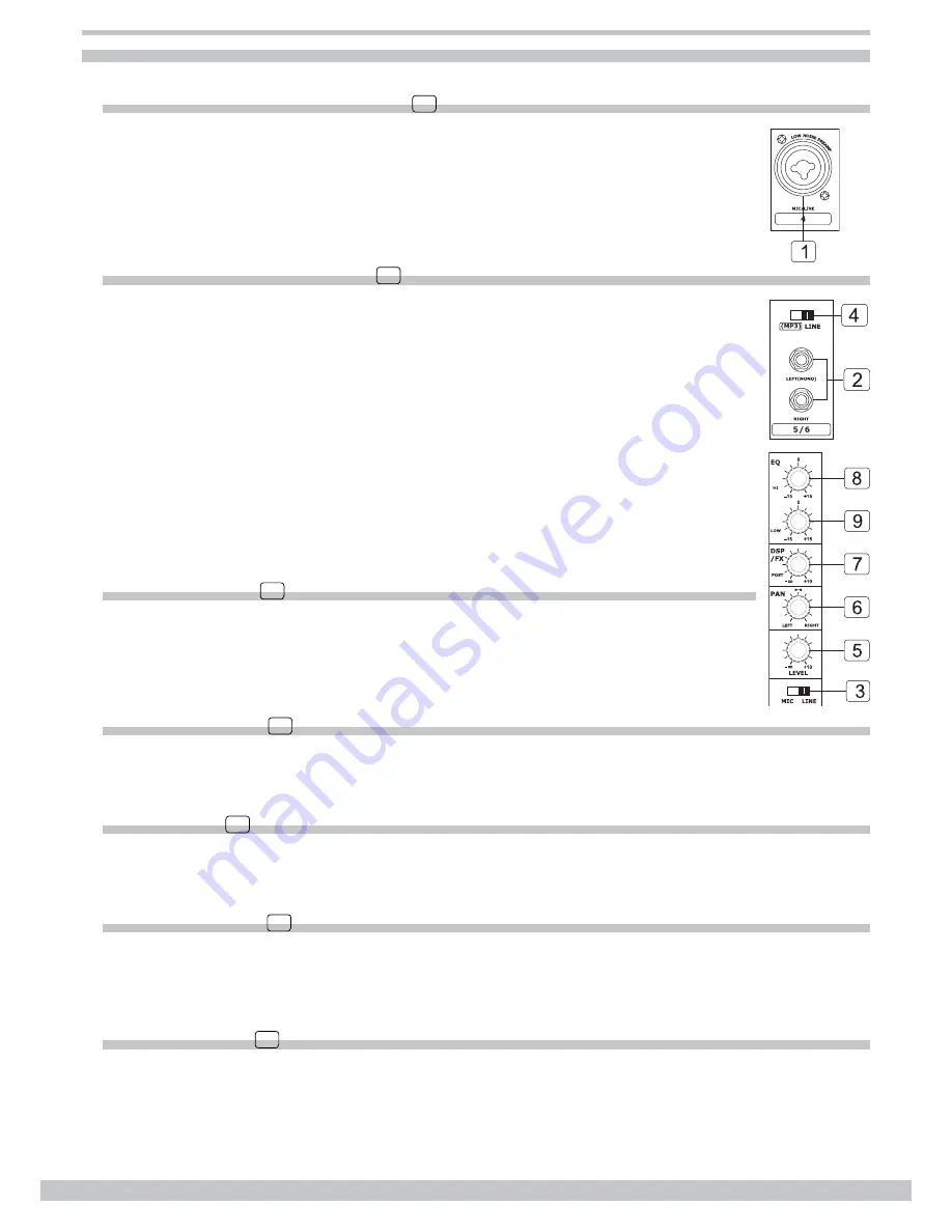
Mono input channels (CH1 to CH4) 

1


The mono input channels 1 to 4 are equipped with balanced combo XLR/¼-inch connectors 

(MIC IN and LINE IN). Use the XLR (MIC IN) socket to connect a low impedance microphone 

or another low level signal. Use the ¼-inch jack socket (LINE IN) to connect either a micro

-

phone or a line level instrument such as a synthesizer, drum machine, effect processor.

Stereo input channel (CH5/6) 

2


The input channels 5 and 6 are organised as stereo pair and provide ¼-inch jack sockets. If 

you connect only the left jack socket, the input will operate in mono mode, that is the mono sig

-

nal will appear on both input channels. You can use these inputs with a stereo keyboard, drum 

machine, etc.

MIC/LINE switch 

3

Use this switch to select the input signal. When using the XLR socket, switch to the MIC posi

-

tion. When using the ¼-inch jack socket, switch to the LINE position.

MP3/LINE switch 

4

Use this switch to select the signal source for the channel 5/6 path. Switch to the MP3 position to use the sig

-

nal from MP3 IN, switch to the position LINE to use the signal from the ¼-inch jack socket.

Level control 

5

This control is used to adjust the overall level of the respective channel. The adjustable range is from –

 to 

+10 dB.

PAN/BAL control 

6

The PANORAMA (or balance) control is used to adjust the stereo image of the signal. Keep this control in cen

-

tre position and your signal will be positioned in the middle of the stage. Turn this control fully counter clock

-

wise and the signal will be present only on the left speaker and vice versa. 

DSP/FX control 

7

This control is configured as POST-FADER, so the audio signal will be affected by the channel level control. 

Via the FX SEND socket, the AUX1 signal can be sent to an external effect device.

Summary of Contents for MEDIA ON The Box

Page 1: ...Owner s Manual MEDIA ONE with 24 bit Digital Effects ...

Page 2: ...ys use proper ready made insulated mains cabling power cord Failure to do so could result in electric shock death or fire If in doubt seek advice from a registered electrician Do not remove any covers Within the unit there are areas where high voltages may be present To reduce the risk of electric shock do not remove any covers unless the AC mains power cord is removed Covers should be removed by ...

Page 3: ...ven surfaces may cause the component and cart combination to overturn Caring for your environment Disposal of the packing material The transport and protective packing has been selected from materials which are environmentally friendly for disposal and can normally be recycled Ensure that any plastic wrappings bags and so on are disposed of safely and kept out of the reach of babies and young chil...

Page 4: ...MEDIA ONE 4 Contents Introduction 5 Features 5 Useful data 5 MEDIA ONE overview 6 Quick start 7 Control elements 9 Audio connections 13 Preset list 14 Technical specifications 15 ...

Page 5: ...rovides 4 microphone inputs with ultra low noise pre amplifiers natural 2 band equalizers and AUX send return In a word it is ideally suited for live sound applications small venues applications live recording and many other musical purposes In order to get the best performances from your MEDIA ONE we recommend you to thoroughly read this Own er s Manual before installation and operation Features ...

Page 6: ...MEDIA ONE 6 MEDIA ONE overview ...

Page 7: ...ers as well as excessive noise Connect a pair of passive speakers to your MEDIA ONE speaker connector inch jack socket You can 3 connect a pair of active speakers directly to your MEDIA ONE left and right main output inch jack sock ets Complete these connections as illustrated in the figure below 4 Before disconnecting the MEDIA ONE always turn off the power switch 5 Do not use solvents to clean y...

Page 8: ...etup diagram WIRELESS MICROPHONE BASS KEYBOARD HEADPHONES DIGITAL EFFECT UNIT DAT OR TAPE RECORDER DAT MIC1 MIC2 Accessory list IEC Power cord 1 Customized speaker cable 5 m 2 Compatible speaker stand optionally available 3 ...

Page 9: ...gnal When using the XLR socket switch to the MIC posi tion When using the inch jack socket switch to the LINE position MP3 LINE switch 4 Use this switch to select the signal source for the channel 5 6 path Switch to the MP3 position to use the sig nal from MP3 IN switch to the position LINE to use the signal from the inch jack socket Level control 5 This control is used to adjust the overall level...

Page 10: ...ed to boost male voice or kick drum and bass guitar Your system will sound much bigger than what it is The gain range goes from 15 dB to 15 dB with a centre frequency of 80 Hz DSP section 12 11 10 Your MEDIA ONE features 16 preset digital effects PRESETS 10 Use this knob to select the effect you wish to perform There are 16 options available WARM HALL BRIGHT HALL WARM ROOM BRIGHT ROOM VOCAL 1 VOCA...

Page 11: ...OUT reaches 10 dB or the start of the compressor of the built in AMP FX RETURNS 16 Use the inch stereo jack socket to return the sound of an effect unit to the main mix You can also use it as an extra auxiliary stereo input FX RET control 17 This control is used to control the volume of the processed signal sent to the main mix bus in a range from to 10 dB FX SEND 18 This inch jack socket is used ...

Page 12: ...g two speakers 4 8 Ω Note The total impedance of the connected speaker system must be between 4 and 8 Ω Do not connect any thing else than speakers to these jack sockets Control elements on the rear side 100 120V 60Hz FUSE T10AL 250V 220 240V 50 60Hz FUSE T5AL 250V AC INPUT AC SELECT POWER ON OFF 24 26 25 Power on off 24 This switch is used to turn the mains power on off AC input 25 This socket is...

Page 13: ...phones 1 4 inch Stereo Jack Plug Strain Clamp Sleeve Tip Sleeve Ground Screen Tip Signal Use for Mono Line In Mono 1 4 Jack Plugs 1 4 inch Mono Jack Plug Strain Clamp Sleeve Tip Ring Sleeve Ground Screen Ring Return Signal Tip Send Signal Use for Insert Points 1 4 inch Stereo Jack Plug 2 Hot 3 Cold 1 Ground Screen seen from soldering side Use for Balanced Mic Inputs For unbalanced use connect pin ...

Page 14: ...ATE Simulates the transducers sound like classic bright vocal plate Pre delay time 10 ms Rev decay time 290 ms 9 STEREO DELAY 1 Recreates the input sound on the stereo output with different time Period 352 ms 10 STEREO DELAY 2 Recreates the input sound on the stereo output with different time Period 238 ms 11 REV DELAY 1 Delay with room effect Delay period 326 ms Rev decay time 290 ms 12 REV DELAY...

Page 15: ...edance Microphone input 3 9 kΩ All other inputs 10 kΩ or greater Tape out 1 kΩ All other outputs 120 Ω Equalization Mono channels Stereo channels High 15 dB 12 kHz 15 dB 12 kHz Low 15 dB 80 Hz 15 dB 80 Hz DSP section A D and D A converters 24 bit DSP resolution 24 bit Type of effects WARM HALL BRIGHT HALL WARM ROOM BRIGHT ROOM VOCAL 1 VOCAL 2 VOCAL 3 PLATE STEREO DELAY 1 STEREO DELAY 2 REV DELAY 1...

Page 16: ... driver Coaxial type 10 woofer 2 voice coil Low frequency driver 1 Neodymium driver 1 voice coil High frequency driver 70 H 70 V spherical hom Connectors Power input with mono jack Static power consumption No output power state at 230 V 32 W Dielectric strength Between live negative earth 1500 VAC at test frequency 50 60 Hz leakage current 5 mA for 1 minute Between live negative IN OUT terminal po...

Reviews: