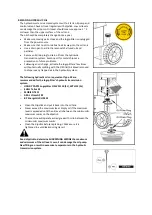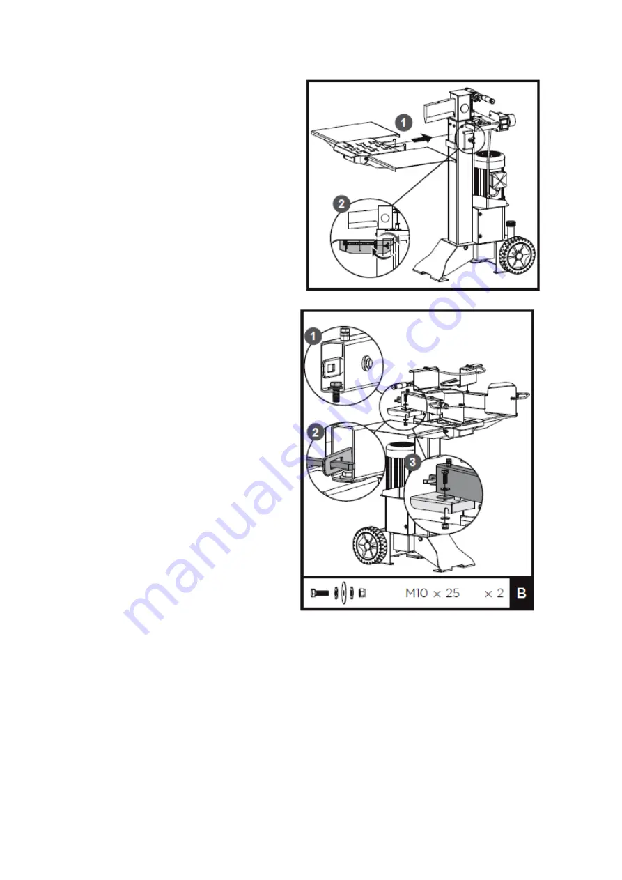
3.
Insert the hooks of the log support table into
the mount brackets.
4.
Tighten the star knob.
CONTROL LEVER
1.
Insert a M10x25 bolt with a flat washer into
the hole on the armguard.
2.
Make sure the lever end goes into the
square slot at the end of the armguard.
Otherwise, the armguard cannot be flexibly
rotated.
3.
Put a big flat washer on support bracket of
the armguard, align the holes. Thread the
bolt which is previously inserted on the
armguard in the first step through the big
flat washer and the bracket. Then put a flat
washer and a nut on the bolt from the
other side. Secure tightly with wrenches.
4.
Follow the same steps to install the
armguard on the other side
.
Summary of Contents for 1938182001
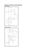
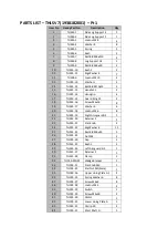
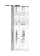
Page 19: ...WIRING HYDRAULIC SYSTEM DIAGRAMS WIRING DIAGRAM HYDRAULIC DIAGRAM ...
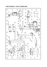
Page 21: ...PARTS DIAGRAM THLSV7 1938182001 ...
Page 27: ......


