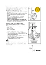
ASSEMBLY
WHEELS
1.
Loosen the bolt on the wheel shaft mount
bracket on the base by turning it counter-
clockwise, until the wheel shaft can be inserted
into the mount bracket.
2.
Insert the wheel shaft into the mount bracket.
3.
Thread the bolt on the bracket into the hole on
the wheel shaft, then secure them together by
tightening the bolt.
4.
Slide the wheel on the shaft. Hold the wheel in
place with a flat washer and a cotter pin from
outside. Bend and spread the cotter pin prongs
in opposite directions.
5.
Put on the wheel cap.
6.
Repeat the same steps to install the wheel on
the other side.
SUPPORT TABLE
1.
Before assembly, loosen the star knob by
turning it counterclockwise
2.
Unfold the log support table, make the
three parts of it at the same surface level.
Summary of Contents for 1938182001
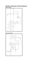
Page 19: ...WIRING HYDRAULIC SYSTEM DIAGRAMS WIRING DIAGRAM HYDRAULIC DIAGRAM ...
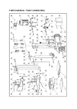
Page 21: ...PARTS DIAGRAM THLSV7 1938182001 ...
Page 27: ......


