background image


STORAGE 

The tiller should be stored in a dry area, out of the reach of children. 
At the end of the season, or the tiller is not going to be used for some time: 


Clean the tiller. 


Wipe over the metal surfaces with an oil-impregnated cloth to protect them from corrosion 
(non-resinous oil) or spray a fine coat of oil onto them from a can. 


Fold the top handle down for ease of storage. 

ADJUSTING AND CHANGING THE TINES 

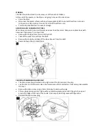
Worn tines can result in poor performance and overload the motor. Sharpen or replace tines with 
new ones if necessary. To remove tines: 


Remove the lock pin from the end of the shaft. 


Take off the outer tine set from the shaft. 


Remove the lock pin and take off the inner tine set from the shaft. 


Reverse above steps to install tines. 


CHECKING TRANSMISSION LUBRICANT 


The drain screw plug is located on the right side of the transmission housing. 


Lay the tiller on its left side & clean the transmission of dirt and debris. If necessary, disassemble 
the tines. 


Remove the drain screw, using a 5mm Allen key to unscrew the plug. 


Fill up using a grease gun & a high quality automotive grade grease until it begins to seep out 
around the edge of the hole of the nozzle. From empty, 60ml of grease will fill gearbox. 


Reinstall the drain screw plug. 


Summary of Contents for THET 193874002

Page 1: ...ORT 01793 333212 IMPORTANT Please read understand this manual payingattention to the safety instructions before use The manufacturer reserves the right to change the product specification and livery a...

Page 2: ......

Page 3: ...before use See the Assembly section for instructions Please check that all parts required for the assembly of this spreader are included If for any reason you believe a part for the assembly is missin...

Page 4: ...uctions for future reference The operator is responsible for following the warnings instructions in this manual and on the product STAY ALERT Do not operate the machine while under the influence of dr...

Page 5: ...night Try to prevent it getting wet or being exposed to humidity Check the power cable regularly to ensure it is not damaged Only use an extension cable which is suitable for outdoor use If the cable...

Page 6: ...p all bystanders animals at least 20 metres away from the machine during operation If approached stop the machine immediately Keep hands feet out of the way of all moving parts Do not place any part o...

Page 7: ...COMPONENTS 1 Trigger Lever 2 Safety Switch 3 Cable Relief 4 Upper Handle 5 Carrying Handle 6 Lower Handle 7 Fender 8 Protective Shield 9 Tines...

Page 8: ...les on the right hand side Re attach the small housing onto the outside of the upper handle and secure using the two black crosshead screws Attach the Middle Handles to the Lower Handle Frame and fast...

Page 9: ...ox STARTING THE MACHINE Plug the machine into the mains If using an extension cable please check that it meets the necessary requirements as stated in this manual When you are at your working area pre...

Page 10: ...Take care when transporting the machine Always carry the tiller to avoid causing damage to the tines when moving over hard ground Switch off the power and clear the tines of all debris roots stones e...

Page 11: ...necessary To remove tines Remove the lock pin from the end of the shaft Take off the outer tine set from the shaft Remove the lock pin and take off the inner tine set from the shaft Reverse above step...

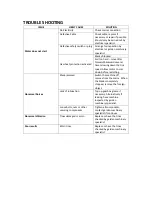
Page 12: ...the tine speed Allow motor to cool down before restarting Abnormal Noises Blade jammed Switch the machine off remove from the mains When the blades completely stopped remove the foreign object Lack o...

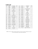
Page 13: ...PARTS DIAGRAM MACHINE NOTE Parts Lists are supplied for information purposes only not all parts are stocked individually we recommend you contact our Spares Team on 01793 333212 for expert advice...

Page 14: ...H165 13 Screw M6x45 4 38 TH165 38 Tines Set 1 1 14 TH165 14 Cable Clip 2 39 TH165 39 Screw M6x16 6 15 TH165 15 Back Cover 1 40 TH165 40 Protective Shield 1 16 TH165 16 Screw ST3x12 1 41 TH165 41 Screw...

Page 15: ...WIRING DIAGRAM...

Page 16: ...placement Spare Parts unless normal wear tear component which are covered for 30 days All machines must be serviced within the first 12 months from the original date of purchase to comply with the war...

Page 17: ...fect of products GJ Handy Co Ltd will never warranty in terms of the merchantability or the fitness for a particular purpose b No person is authorised to make any warranties representations or promise...

Page 18: ...ed to EN 55014 1 2006 A1 A2 EN 55014 2 1997 A1 A2 EN 61000 3 2 2006 A1 A2 EN 61000 3 3 2013 EN 60335 1 2012 EN 709 1997 A4 EN 62233 2008 ZEK 01 4 08 11 11 Name of the Notified Body T V Rheinland LGA P...

Page 19: ......

Page 20: ...Mon Fri 8 00am to 5 30pm excl Bank Holidays Email customerservice handydistribution co uk To see our range of garden machinery equipment visit www thehandy co uk Making gardening easier affordable si...

Reviews: