SET UP & PREPARATION FOR OPERATION
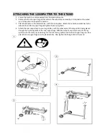
Bolt the Support Leg to the Log Splitter, lift the log splitter by the Log Pusher & Handle & place it
on a 60 – 75cm high, stable, flat and level work surface.
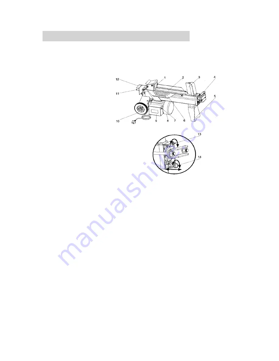
Familiarise yourself with the controls and features of this log splitter in the illustrations.
1.
Log Pusher
2.
Work Table
3.
Wedge
4.
Handle
5.
Support Leg
6.
Log Retaining Plates
7.
Switch
8.
Motor
9.
Electric Motor Switch Case
10.
Wheels (short distances
ONLY).
11.
Hydraulic Control Lever
12.
Control Lever Guard
13.
Bleed Screw
14.
Oil Drain Bolt w/ Dipstick
15.
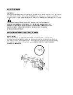
Max Pressure Limiting
Screw
Summary of Contents for THLS-6-PLUS
Page 2: ......
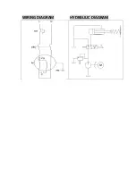
Page 11: ...WIRING DIAGRAM HYDRAULIC DIAGRAM ...
Page 17: ...PARTS DIAGRAM THLS 6 193893001 ...
Page 23: ......


