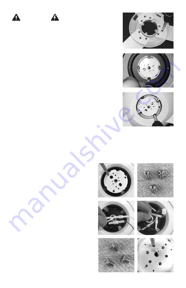
Depending on the date of manufac-
ture, your fan may have been supplied
with separate terminals for each wire.
If so, join ends of bridge connector
wires with wire leads from fan.
Position wires so that connectors are
flat and inside of three posts in the
center cavity area.
Remove white fastener plate held by
three screws shown here.
5
5
WARNING
See Page 2
POWER OFF
Circuit Breaker
3
Set fan body on either piece of packing foam,
bottom side up. Remove four, phillips head rotor
screws from motor and set aside for Step 4.
Do NOT remove the white multi-point
(star-drive) screws.
Rotate motor so that the empty screw holes from
Step 3 are aligned with the notches in the center
hub. Carefully set rotor and blade assembly on
motor so that attachment tabs are positioned
over motor holes. Secure rotor to motor using
the four screws from Step 3.
If installing optional #271 LED Light Kit, follow the steps below. Otherwise,
skip this section and proceed to Step 6.
Note:
If the parts you received are different than what is listed/pictured here,
you may have a prior version of the light kit assembly. Please contact customer
service for instructions.
4
5
Carefully insert blades into rotor slots, and using
pan head screws from hardware package, secure
blades to rotor.
2
Place light plate over wire connectors
so that the three, threaded posts
are seated in the taller stand-offs on
back of light light plate and two-pin
connector passes through center
hole. With three countersink screws,
fasten light plate to fan.


