8
C.
Using the A-frame Positions
1. Unlock both hinge locks. (See Figures A-4 & A-5)
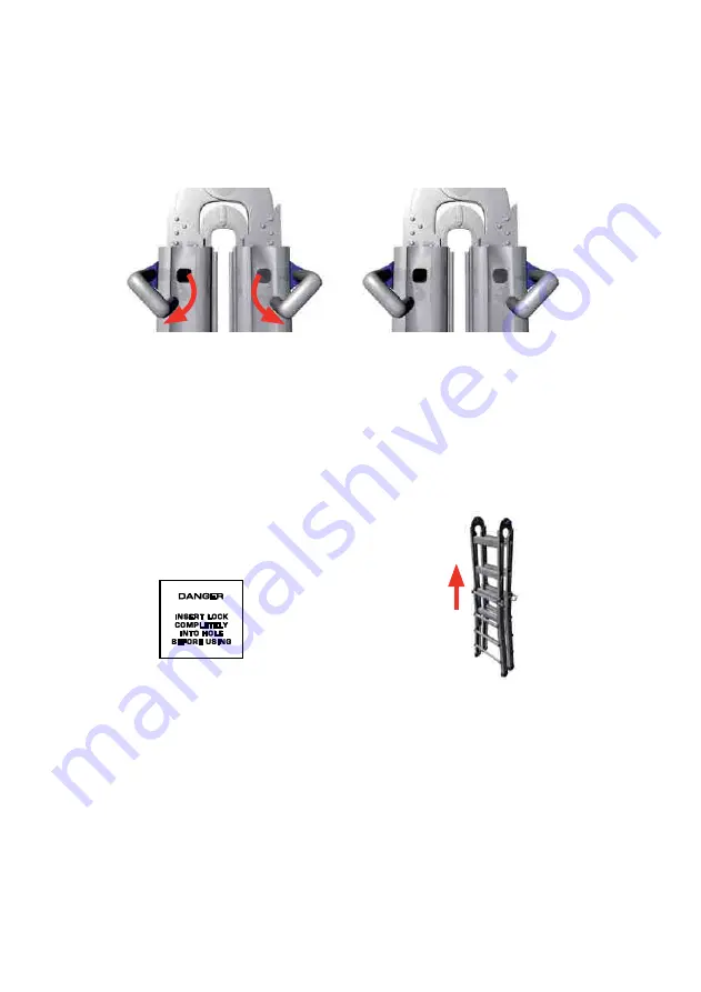
2. While the ladder is in the storage position, pull out the four Lock Assemblies from the
rung holes and rest them on the outside ladder rail.
(See Figures C-1 and C-2).
3. Raise the inner ladder to the required height.
SAFETY PRECAUTION:
READ THE WARNING STAMPED BELOW
EACH LOCK ASSEMBLY
4. At the required height align the nearest inner and outer rung holes.
5. With the inner and outer ladder aligned hold the ladder in one hand and re-insert the
opposite Lock with the other hand.
6. Change hands and re-insert the other Lock Assemblies.
(See Figure C-3).
7. Pull the ladder halves apart until the hinges lock into place and the ladder stands in the
A-Frame position.
8. Insert the work platform as a spreader to brace the ladder.
(120KG MODEL ONLY)
9. To reset the ladder to the storage position, reverse the procedures and position as seen
in Figure A-1.
SAFETY PRECAUTION:
ALWAYS HOLD THE INNER LADDER WHENEVER CHANGING THE LEG
LOCK ASSEMBLIES OTHERWISE IT WILL SLIDE & HIT THE GROUND.
DO NOT USE THE OUTER OR INNER SECTIONS OF THE LADDER AS A
SEPARATE STEPLADDER.
D.
Using the Extension Ladder Position
1. From the storage position, unlock the hinges (as shown in Figures A-4 and A-5) and
rotate the legs until both hinges lock into place at the extension position. (See Figure A-7)
2. NOTE: The hinge will first lock into the A-frame position, unlock the hinges again and
continue rotating to the extension position.
Figure C-3
Figure C-1
Figure C-2


