background image

2

1

PWA2.3x8mm

PWA2.3x8mm 

Screw

d1.5xD6.5mm 

Silicon Grommet

4

4

16

Canopy

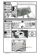
First insert the grommet to the canopy then apply screw.

Silicon Grommet

  d1.5xD6.5mm

Apply double-sided tape

Pilot

Adjust the wing and fuselage configuration as 

shown in the diagrams.

B

B'

C

C'

A = A '
B = B '

C = C '

Wing Setting

17

A

A'

P.11

1mm

GA026PO29451405

All manuals and user guides at all-guides.com

Summary of Contents for SPITFIRE 160

Page 1: ...030 mm Wing Area 1138 sq in 73 4 sq dm Flying Weight 13 lbs 5850 g Fuselage Length 68 in 1730 mm Requires 2 stroke 1 60 engine 6 channel radio w 9 servos It is designed for maximum performance Please...

Page 2: ...before you begin so you will have an overall idea of what to do Symbols used throughout this instruction manual comprise of the following 1 2 3 P 1 SPITFIRE 160 INDEX BEFORE YOU BEGIN PARTS LIST ASSE...

Page 3: ...ASHER d6xD15mm 4 pcs BLIND NUT M6xD18mm 4 pcs 10 FUEL TANK 800cc PL1111810G 1 set CABLE TIE 1 5x8x500mm 1 pc DOUBLE SIDE TAPE 40x160mm 1 pc PLYWOOD 3x42x125mm For Fixing Fuel Tank 1 pc BALSA 8x8x42mm...

Page 4: ...asher Covering Film 8 PWA2 3 8mmScrew x PWA2 3x8mm d2xD5mm Washer PM2x8mm M2 NUT Bottom View Aileron Servo lead 2mm 1mm Pre glued L Retract Servos R Wheel Down Wheel up Wheel Down Wheel up 32mm Travel...

Page 5: ...8x110mm PB2x14mm Screw PWA2x8mm Screw PB2x25mm Screw 6 6 The existing slots are for 2 channels mixing operation of the flaps Straper Push Rod 1 8x105mm P 4 PWA2x8mm 16 PB2x14mm 1 5mm Fuel Tube 6x5mm...

Page 6: ...eted Stabilizer Elevator 4 A A A A PA3x12mm Screw 2 d3xD7mm Washer 2 PA3x12mm Stabilizer Tube D9 5x257mm d3xD7mm 97mm 60mm Completed Pre glued d3xD7mm PA3x12mm 2mm GA026PO29451405 All manuals and user...

Page 7: ...odels tri horn are pre drilled Please look for pin hole marks at under side of control surfaces 2 5mm 3mm Set Screw PA3x12mm Elevator Pushrod 7 PB 2x25 mm Screw 6 3x3mm Set Screw 1 PB2x25mm Fuel Tube...

Page 8: ...pilot holes for World Models tri horn are pre drilled Please look for pin hole marks at side of control surfaces Rudder Pullwire 8 PM 2x30mm Screw 3 M2 Nut 3 PM2x30mm M2 Nut Clevis Rigging Coupler 1 8...

Page 9: ...Insert Lock Nut 4 8 4 8 d4xD12mm Washer KM3x20mm Washer M3 Nylon Insert Lock Nut 8 ANTI VIBRATION MOUNT INSTALLATION M3 KM3x20mm Counter Sink 4 1mm 5 1mm 3 2mm Make sure the rounded edges are facing t...

Page 10: ...e diagram Front Throttle pushrod 1 2x350mm Bottom View Throttle Servo Plywood 3x12x119mm Elevator Servo Pushrod Connector J1 Pushrod 1 8x70 J1 J2 KM2x8mm M2 Nut Elevator Pushrod 1 8x70mm Plastic Tube...

Page 11: ...HM4x40mm Screw M3NylonInsertLockNut M3x15mm Screw 8 2 2 2 2 d3xD7mm Washer 2 M3 Nut 2 d4xD15mm Washer HM4x40mm d4xD15mm Wing Protection Bottom View Bottom View Wing Tube D25 4x670mm Wing Tube D9 5x 32...

Page 12: ...ert the grommet to the canopy then apply screw Silicon Grommet d1 5xD6 5mm Apply double sided tape Pilot Adjust the wing and fuselage configuration as shown in the diagrams B B C C A A B B C C Wing Se...

Page 13: ...d to be powered by 1 60 2 stroke glow engine using a more powerful engine does not mean better performance In fact over powered engine may cause severe damage and injuries Warning When Flaps are lower...

Page 14: ...age the supporting structure P 13 LINKAGE CONNECTOR HW7111050 HW7111060 Drill 2mm hole at servo horn Insert linkage connector into servo horn Make sure shoulder of screw is cleared from servo horn Add...

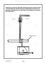
Page 15: ...wire please insert a round metal bar into the spring coil and apply force there as leverage Bending the wire directly may damage the mounting block structure l Round metal bar P 14 GA026PO29451405 All...

Page 16: ...THE WINGS MAKER www thewingsmaker com GA026PO29451405 All manuals and user guides at all guides com a l l g u i d e s c o m...

Reviews: