background image

P.12

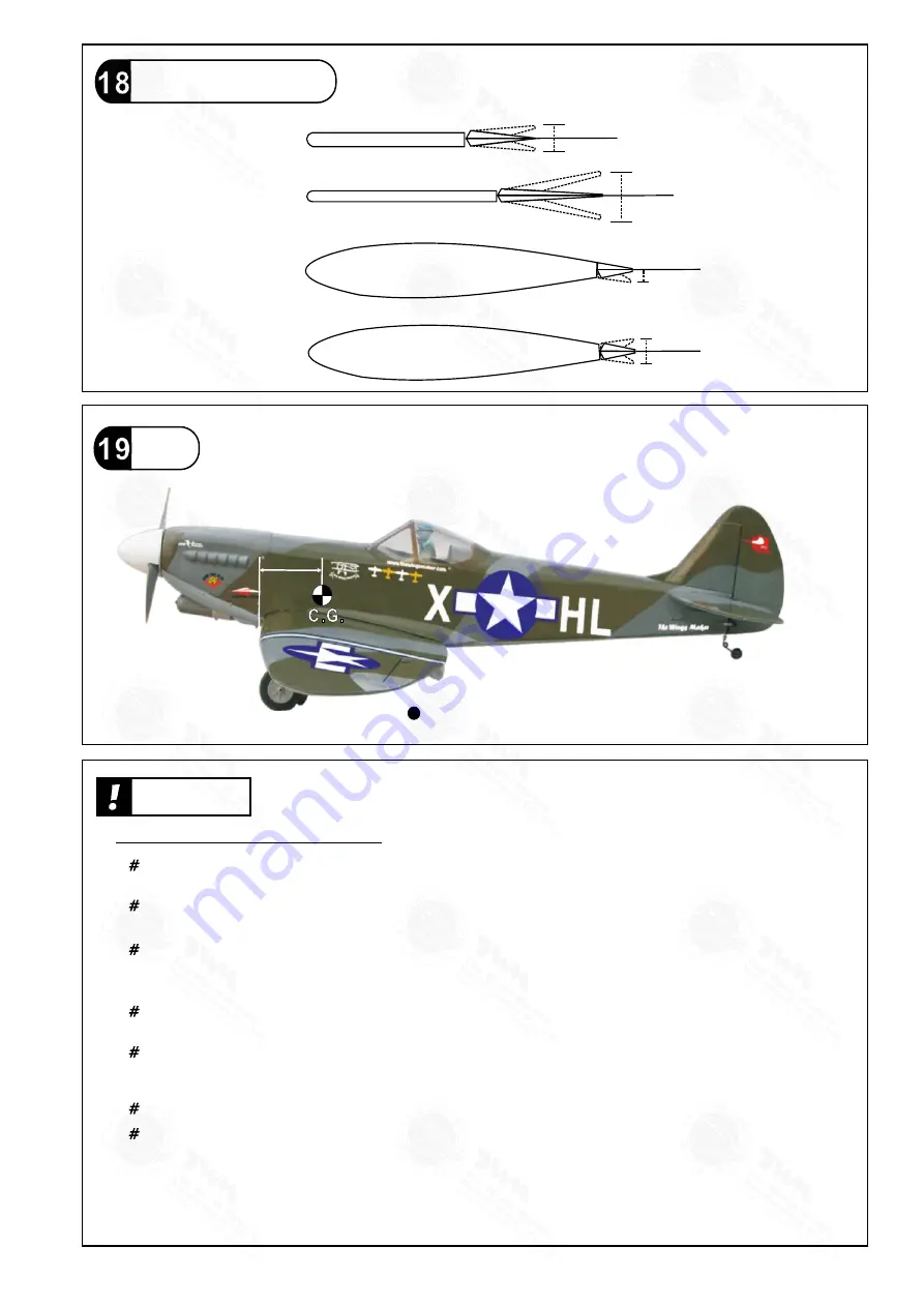
Control Throws

Adjust the control throws as shown in the diagram. 

These throws are good for general flying.  You can 

adjust according to your personal preference.

C.G.

116mm

4.6in

25mm

25mm

55mm

55mm

Elevator

Rudder

35mm

20mm

20mm

Ailerons ( away from fuselage )

Flaps (near fuselage )

Important Safety Precautions

First time flyer should never fly by himself / herself. Assistance from experienced flyer is  


absolutely necessary.
Pre - flight adjustment must be done before flying, it is very dangerous to fly a badly 

adjusted aircraft.

pre - 

Make sure the air field is spacious, never fly the plane too close to people and never get 

too close to a running propeller.
If you find wrinkles on the covering as a result of weather changes, you can use hot iron 

to remove the wrinkles.  Please begin with lower temperature setting and gradually raise 

the  temperature until the wrinkles are gone.  Too hot an iron may damage the covering.
Check and re-tighten up all factory assembled screws, use thread locker if applicable. 

SPITFIRE 160

 is specially designed to be powered by 

1.60 2

-stroke glow engine, using 

a more powerful engine does not mean better performance.  In fact, over powered engine 

may cause severe damage and injuries.


Warning!

When Flaps are lowered, nose of model will rise. The nose-up varies with the speed at which

the model is flying when you lower the flaps and the extent to which they are lowered.  Check

effect of flaps at higher altitude to avoid surprises during landing.  You may apply down trim

of the elevator to compensate for the nose-up effect when lowering the flaps.  Taking off with 

flaps lowered is not recommended, as the increased drag may require a longer runway and

more engine power for the model.


Measure C.G. with the wheels in retracted position.

http://www.theworldmodels.com/para/instruction/instructionManuals.php

The ideal C.G. position is 

116mm (4.6 in)

behind the leading edge measured 

at where the wing meets the fuselage.  In order to obtain the C.G. specified, 

add weight to the fuselage or move the battery position.  Check the C.G. before

 flying.

If you are converting this model to electric, please move the C.G. forward  10% of 

current C.G. distance from leading edge to compensate for weight of fuel.


GA026PO29451405

All manuals and user guides at all-guides.com

Summary of Contents for SPITFIRE 160

Page 1: ...030 mm Wing Area 1138 sq in 73 4 sq dm Flying Weight 13 lbs 5850 g Fuselage Length 68 in 1730 mm Requires 2 stroke 1 60 engine 6 channel radio w 9 servos It is designed for maximum performance Please...

Page 2: ...before you begin so you will have an overall idea of what to do Symbols used throughout this instruction manual comprise of the following 1 2 3 P 1 SPITFIRE 160 INDEX BEFORE YOU BEGIN PARTS LIST ASSE...

Page 3: ...ASHER d6xD15mm 4 pcs BLIND NUT M6xD18mm 4 pcs 10 FUEL TANK 800cc PL1111810G 1 set CABLE TIE 1 5x8x500mm 1 pc DOUBLE SIDE TAPE 40x160mm 1 pc PLYWOOD 3x42x125mm For Fixing Fuel Tank 1 pc BALSA 8x8x42mm...

Page 4: ...asher Covering Film 8 PWA2 3 8mmScrew x PWA2 3x8mm d2xD5mm Washer PM2x8mm M2 NUT Bottom View Aileron Servo lead 2mm 1mm Pre glued L Retract Servos R Wheel Down Wheel up Wheel Down Wheel up 32mm Travel...

Page 5: ...8x110mm PB2x14mm Screw PWA2x8mm Screw PB2x25mm Screw 6 6 The existing slots are for 2 channels mixing operation of the flaps Straper Push Rod 1 8x105mm P 4 PWA2x8mm 16 PB2x14mm 1 5mm Fuel Tube 6x5mm...

Page 6: ...eted Stabilizer Elevator 4 A A A A PA3x12mm Screw 2 d3xD7mm Washer 2 PA3x12mm Stabilizer Tube D9 5x257mm d3xD7mm 97mm 60mm Completed Pre glued d3xD7mm PA3x12mm 2mm GA026PO29451405 All manuals and user...

Page 7: ...odels tri horn are pre drilled Please look for pin hole marks at under side of control surfaces 2 5mm 3mm Set Screw PA3x12mm Elevator Pushrod 7 PB 2x25 mm Screw 6 3x3mm Set Screw 1 PB2x25mm Fuel Tube...

Page 8: ...pilot holes for World Models tri horn are pre drilled Please look for pin hole marks at side of control surfaces Rudder Pullwire 8 PM 2x30mm Screw 3 M2 Nut 3 PM2x30mm M2 Nut Clevis Rigging Coupler 1 8...

Page 9: ...Insert Lock Nut 4 8 4 8 d4xD12mm Washer KM3x20mm Washer M3 Nylon Insert Lock Nut 8 ANTI VIBRATION MOUNT INSTALLATION M3 KM3x20mm Counter Sink 4 1mm 5 1mm 3 2mm Make sure the rounded edges are facing t...

Page 10: ...e diagram Front Throttle pushrod 1 2x350mm Bottom View Throttle Servo Plywood 3x12x119mm Elevator Servo Pushrod Connector J1 Pushrod 1 8x70 J1 J2 KM2x8mm M2 Nut Elevator Pushrod 1 8x70mm Plastic Tube...

Page 11: ...HM4x40mm Screw M3NylonInsertLockNut M3x15mm Screw 8 2 2 2 2 d3xD7mm Washer 2 M3 Nut 2 d4xD15mm Washer HM4x40mm d4xD15mm Wing Protection Bottom View Bottom View Wing Tube D25 4x670mm Wing Tube D9 5x 32...

Page 12: ...ert the grommet to the canopy then apply screw Silicon Grommet d1 5xD6 5mm Apply double sided tape Pilot Adjust the wing and fuselage configuration as shown in the diagrams B B C C A A B B C C Wing Se...

Page 13: ...d to be powered by 1 60 2 stroke glow engine using a more powerful engine does not mean better performance In fact over powered engine may cause severe damage and injuries Warning When Flaps are lower...

Page 14: ...age the supporting structure P 13 LINKAGE CONNECTOR HW7111050 HW7111060 Drill 2mm hole at servo horn Insert linkage connector into servo horn Make sure shoulder of screw is cleared from servo horn Add...

Page 15: ...wire please insert a round metal bar into the spring coil and apply force there as leverage Bending the wire directly may damage the mounting block structure l Round metal bar P 14 GA026PO29451405 All...

Page 16: ...THE WINGS MAKER www thewingsmaker com GA026PO29451405 All manuals and user guides at all guides com a l l g u i d e s c o m...

Reviews: