background image

Wing Span
Wing Area
Flying Weight
Fuselage Length

66.5 in / 1690 mm

882 sq in / 56.9 sq dm

57.0 in /1450 mm

5.5 lbs / 2500 g

Specifications

INSTRUCTION MANUAL

0.40-0.46 cu  in  displacement 2-stroke

.

.

Requires : 4-channel radio w/ 5 standard servos

Warning !This model is not a toy.

It is designed for maximum performance.  Please seek advice if one is not familiar with this kind
of engine powered precision model.  Operating this model without prior preparation may cause
injuries.  Remember, safety is the most important thing.  Always keep this instruction manual at 
hand for quick reference.

* Specifications are subject to change without notice.*

The


World


Models

Manufacturing


Co

., 

LTD

.

w w w

.

t h e w o r l d m o d e l s

.

c o m

ALMOST-READY-TO-FLY (ARF)  SERIES

MADE IN CHINA

FACTORY PRE-FABRICATED

E A D

R

-

Y

T

- T

S

O

O

- F

M

L

L

Y

A

A095PO

25881103

Summary of Contents for SUPER STUNTS

Page 1: ...ormance Please seek advice if one is not familiar with this kind of engine powered precision model Operating this model without prior preparation may cause injuries Remember safety is the most important thing Always keep this instruction manual at hand for quick reference Specifications are subject to change without notice The World Models Manufacturing Co LTD www theworldmodels com ALMOST READY T...

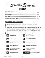
Page 2: ...ement The manufacturer will replace any defective parts but will not extend to the parts that are good before gluing to defective parts during assembly Warranty will not cover any parts modified by customer INDEX BEFORE YOU BEGIN PARTS LIST ASSEMBLY SAFETY PRECAUTIONS P 1 P 2 P 10 BEFORE YOU BEGIN Read through the manual before you begin so you will have an overall idea of what to do Symbols used ...

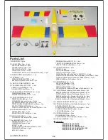
Page 3: ...M PLATE 1mm 1 pc SCREW PM2x10mm 4 pcs WASHER d2xD5mm 4 pcs M2 NUT 4 pcs SOCKET HEAD SCREW M3 5x30mm 4 pcs WASHER d3 5xD8mm 8 pcs M3 5 NUT 8 pcs SPINNER Ø57mm PL2111057 1 set THROTTLE PUSHWIRE Ø1 2x340mm 1 pc PLASTIC TUBE d2xD3x180mm 1 pc 12 SCREW PM2x16mm 2 pcs M2 NUT 2 pcs FUELTUBE Ø6x5mm 2 pcs CLEVIS L PL4112102 2 pcs HORN Non Base For Rudder L PL4113101 2 sets RIGGING COUPLER Ø1 8x27mm w Thread...

Page 4: ...rfaces in contact Use a stick to apply the glue to inner side of wing joiner sleeve and apply the glue to wing joiner before putting them together Wing joiner not glued properly will lead to wing failure and plane crash Ø1mm pilot holes for World Models horn are pre drilled Please look for pin hole marks at under side of control surfaces Straper Pushrod Ø1 8 x 175mm Fuel Tube Ø6 x 5mm PB2 x 12mm C...

Page 5: ...es of each hinge Apply instant type CA glue to both sides of each hinge C C C C P 4 A A A A Temporary install the main wing adjust leveling of the stabilizer to make it as parallel to the main wing as possible Stabilizer Elevator Vertical Fin Rudder BALSA Fin Tip 6x54 4x223 5mm A095PO25881103 ...

Page 6: ...m d4xD9mm Washer Engine Mount PL5111050 Blind nuts are off centered to keep the spinner at the fuselage axis Apply thread locker to screws 3mm Set Screw 3mm Set Screw 8 2 3mm Set Screw 4 1mm Collar 4 1mm Collar Front Landing Gear PLYWOOD 7 5 x 7 5 x 18mm Cable Tie 1 5x5x400mm 40x100mm Double sided Tape Completed A095PO25881103 ...

Page 7: ...r 3mm Set Screw 9 10 P 6 2mm PA3x12mm Screw 4 4 4 1mm Collar Main Landing Gear Main Wheels Engine 11 PM2x10mm Screw Installed Engine Position Spinner 52mm 118mm 4 65 in d3 5xD8mm Washer d2xD5mm Washer M3 5 Nut Completed M3 5x30mm d3 5xD8mm Washer M3 5 Nut M3 5x30mm Socket Head Screw Mounting Plate 12x20mm A095PO25881103 ...

Page 8: ...m Fuel Tube Ø6x5mm 2mm PB2x16mm Screw 2 Ø1mm pilot holes for World Models horn are pre drilled Please look for pin hole marks at under side of control surfaces Bottom View PB2x16mm Horn Elevator Pushrod Ø1 8x760mm Plywood 6x62x98 3mm Plywood 6x62x96 4mm Plywood 6x42x96mm Balsa 6x6x42mm Balsa 5x5x62mm Balsa 5x5x62mm 14 Servos TWM Pl8210010 CLEVIS WRENCH TWM Pl8210010 CLEVIS WRENCH Horn Wire 1x860mm...

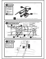
Page 9: ...Servo Rudder Servo Elevator Servo Straper Fuel Tube Ø6x5mm Sponge Receiver Battery Front Front Wheel Pushrod Elevator Pushrod Rigging Coupler Ø1 8x27mm Copper Tube d2 5xD3 2x8mm Radio Equipment 16 Install and arrange the servo as shown in the diagram HM4x35mm Screw D4xD12mm Washer 2 2 HM4x35mm d4xD12mm Washer Wing Protection 3x30x97mm 4mm Main Wing 17 2mm Washer 2mm 2mm Washer Charge Receptacles K...

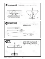
Page 10: ...s shown in the diagram These throws are good for general flying You can adjust according to your personal preference C G The ideal C G position is 105mm 4 13 in behind the leading edge measured at where the wing meets the fuselage In order to obtain the C G specified add weight to the fuselage or move the battery position Check the C G before flying C G 20 105 mm 4 13 in C G A095PO25881103 ...

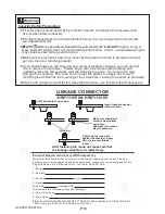
Page 11: ...ing at the same time causing the seams to pull away Check and re tighten up all factory assembled screws use thread locker if necessary 0 40 0 46 more Warning LINKAGE CONNECTOR HW7111050 HW7111060 After fastening the round nut make sure that the linkage connector can rotate freely Product Registration Form US Customers We would like to share with you any relevant information regarding your model i...

Page 12: ...The World Models Manufacturing Co LTD www theworldmodels com A095PO25881103 ...

Reviews: