background image

P. 1

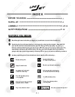
INDEX

BEFORE YOU BEGIN

P.1

PARTS LIST

P.2

SAFETY PRECAUTIONS

P.10

BEFORE YOU BEGIN

Cut off shaded portion.

Ensure smooth non-binding

movement while assembling.

Apply instant glue

(C.A.glue, super glue.)

Assemble left and right

sides the same way.

Peel off shaded portion

covering film.

Pay close attention here!

Apply epoxy glue. 

Must be purchased separately !

Drill holes with the specified

diameter (here:  3mm).

ASSEMBLY

P.3-P.10

Check all parts.  If you find any defective or missing parts contact your local dealer.  Please DRY FIT

and check for defects for all parts that will require CA or Epoxy for final assembly.  Any parts you

find to be defective after the gluing process may be difficult to remove for warranty replacement.  The

manufacturer will replace any defective parts, but will not extend to the parts that are good before 

gluing to defective parts during assembly.  Warranty will not cover any parts modified by customer.

Read through the manual before you begin, so you will have an overall idea of what to do.

Symbols used throughout this instruction manual comprise of the following : -

1

2

3

Pierce the shaded portion

covering film.

3mm

Do not overlook this symbol !

Warning!

Apply thread locker

Summary of Contents for UniJet

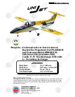
Page 1: ...reparation may cause injuries Remember safety is the most important thing Always keep this instruction manual at hand for quick reference Requires 4 channel radio w 4 micro servos Ducted Fan Propulsion Unit PL6800010 and Outrunner Motor KM0283110 30A burst 35A brushless ESC 3 cells 11 1V 15C discharge 2100 mAh Li Po battery charger Specifications are subject to change without notice INSTRUCTION MA...

Page 2: ...local dealer Please DRY FIT and check for defects for all parts that will require CA or Epoxy for final assembly Any parts you find to be defective after the gluing process may be difficult to remove for warranty replacement The manufacturer will replace any defective parts but will not extend to the parts that are good before gluing to defective parts during assembly Warranty will not cover any p...

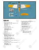
Page 3: ...ANDING GEAR 1 set PLASTIC COLLAR d1 1xD5x2mm 2 pcs FRONT WHEEL PL3111250 Ø23mm 1 pc SCREW PA2x8mm 2 pcs 8 PUSHROD Ø1 2x440mm w Threads For Rudder Servo 1 pc HORN 1 set SCREW PB2x12mm 2 pcs 9 PUSHROD Ø1 2x533mm w Threads For Elevator Servo 1 pc HORN 1 set SCREW PB2x8mm 2 pcs SCREW PA2x5mm 3 pcs PVC COVER 0 5mm 1 pc 10 PUSHROD Ø0 8x206mm For Front Landing Gear 1 pc PLASTIC TUBE d2xD3x140mm 1 pc CLEV...

Page 4: ...rfaces 4 8 PA1 7x8mm Screw PB2x16mm Screw Straper Fuel Tube d2xD4x4mm Please choose either 02L 02R or 03L 03R or 04L 04R that suits your servo 02L 03L 04L 02R 03R 04R Apply instant type CA glue to both sides of each hinge Bottom View Bottom View Fuel Tube Clevis PB2x16mm Horn Pushrod Ø1 4x42mm d2xD4x4mm PA1 7x8mm TWM PL8210010 CLEVIS WRENCH Code No SV2031 Micro Servo ...

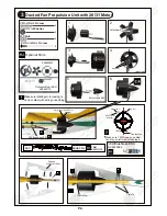
Page 5: ... sure rotating motor casing is not in contact with wiring or anything PM2x5mm PM3x12mm PM3x12mm M3 Nut M3x6mm Rear View 4 d3xD7mm Washer d3xD7mm Washer Plywood 3x67 8x217 8mm PWA2 3x8mm Cable Tie 1 5mm M W T M W T M W T M W T M W T M W T 6 30A Brushless ESC Outrunner Motor 28 31 KM0283110 PL6800010 Motor Lead Exit Optional Parts Solder Solder TWM KP0011310 ESC Ducted Fan 30A Brushless ESC KC2030A0...

Page 6: ...s of each hinge Temporary install the main wing adjust leveling of the stabilizer to make it as parallel to the main wing as possible Bottom View Main Landing Gear 6 PA2x8mm Screw 2 6mm Collar 4 4 PA2x8mm 1mm Front A A A A C C C C 3mm Set Screw 2 6mm Collar Apply instant type CA glue to both sides of each hinge Bottom View ...

Page 7: ... Ø1mm pilot holes for World Models horn are pre drilled Please look for pin hole marks at under side of control surfaces Ø1mm pilot holes for World Models horn are pre drilled Please look for pin hole marks at under side of control surfaces Rudder Pushrod Ø1 2x440mm Horn PB2x12mm 120mm 55mm PB2x8mm Elevator Pushrod Ø1 2x533mm Ø1mm pilot hole is pre drilled Please look for pin hole marks at under s...

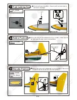
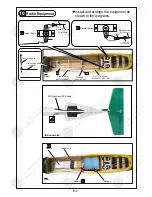
Page 8: ...g Gear Pushrod Front Landing Gear Pushrod Ø0 8x206mm Front Plywood 2x9 4x15mm Plastic Tube d2xD3x140mm Elevator Servo Elevator Pushrod Ø1 2x533mm Fuel Tube d2xD4x4mm Rudder Pushrod Ø1 2x440mm Rudder Servo Fuel Tube d2xD4x4mm Clevis Clevis Bottom View Front Battery Battery Tie Sponge Receiver 30A Brushless ESC Lead ...

Page 9: ...Main Wing 11 Lead To Aileron Servo Wing Tube Ø9 6x284mm Rubber Band Eye Screw PA2 5x10x23mm 1 5mm P 8 Front Front Front Bottom View ...

Page 10: ...P 9 Wing Setting 13 Adjust the wing and fuselage configuration as shown in the diagrams A A B B C C A A B B C C Canopy w Cockpit Assembly 12 Completed Pilots ...

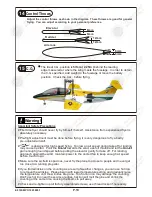
Page 11: ...ler If you find wrinkles on the covering as a result of weather changes you can use hot iron to remove the wrinkles Please begin with lower temperature setting and gradually raise the temperature until the wrinkles are gone Too hot an iron may damage the covering Don t use hot iron near the seams or edges hot iron will melt the glue and shrink the covering at the same time causing the seams to pul...

Page 12: ..._____________ 2 Address ____________________________________________ 3 Phone ____________________ E mail __________________ 4 Model ______________________________________________ Wing QC __________ Fuselage QC _______________________ QC numbers are stamped on wing and fuselage 5 Date of Purchase _____________________________________ 6 Store Name _________________________________________ Please cal...

Page 13: ...ode No Size Package PL6800010 1 set Operating Voltage Current 12V 30A 35A Burst Thrust Approx 560A Weight 60g without motor Rotor diameter 67 mm Outer casing diameter 74 mm Color Black Outrunner 28 31 for ducted fan Code No Size Package KM0283110 D28 x 31 mm 1 set Kv rpm V 3600 Operating Power 375W Operating Voltage 6 15V Operating Current 30A Peak Current 35A max 15 sec Internal Resistance 25 m o...

Page 14: ...http www theworldmodels com E272XMPO19830903 ...

Reviews: