background image

A345PO32021803

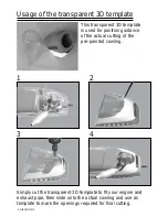
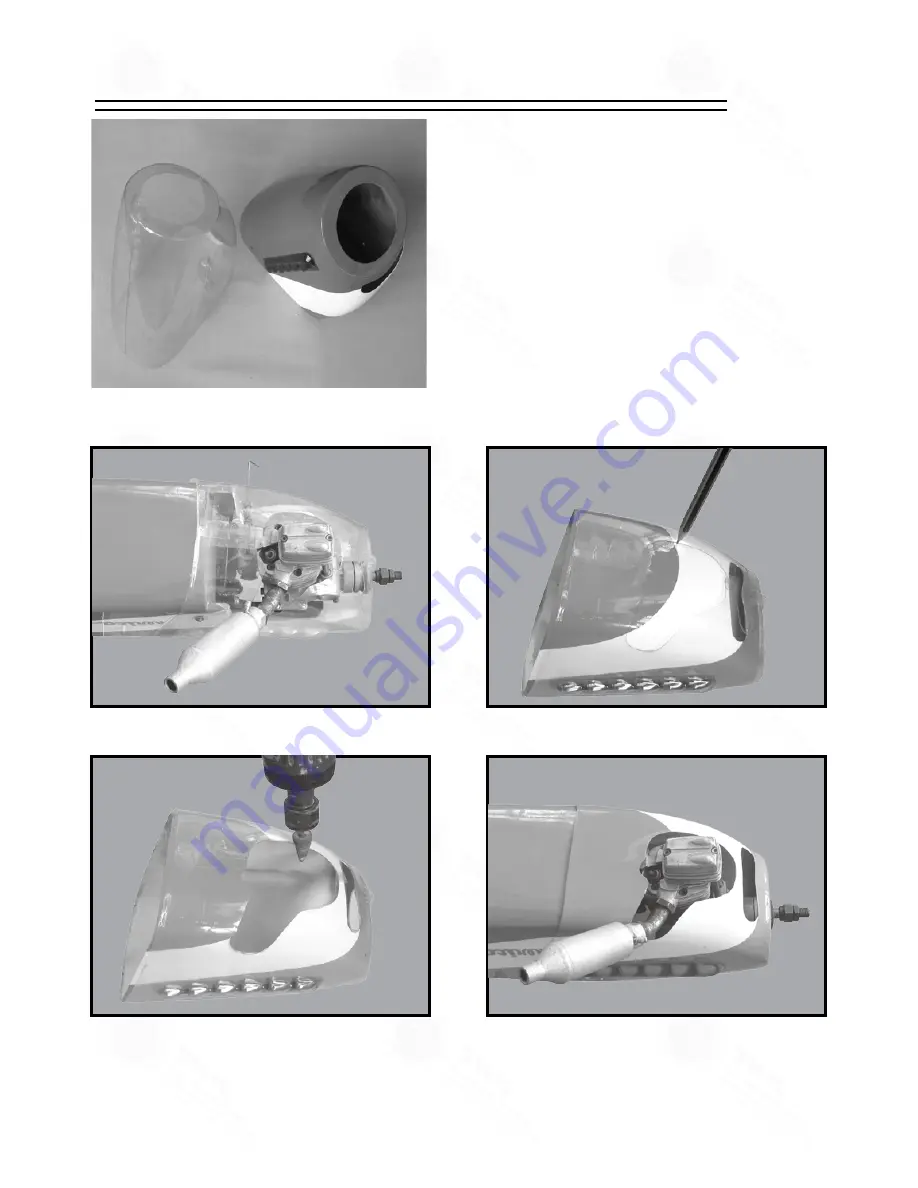
This transparent 3D template
is used for position guidance
of the actual cutting of the
pre-painted cowling.

Usage of the transparent 3D template

Simply cut the transparent 3D template to fit your engine and 
exhaust pipe, then slide onto the actual cowling and use as 
template to mark the openings required for final cutting.

1

2

3

4

Summary of Contents for Vendetta A345

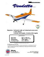
Page 1: ... keep this instruction manual at hand for quick reference Specifications are subject to change without notice INSTRUCTION MANUAL Wing Span Wing Area Flying Weight Fuselage Length 56 5 in 1435 mm 558 sq in 36 sq dm 7 3 Ib 3350 g 51 in 1290 mm Specifications FACTORY PRE FABRICATED ALMOST READY TO FLY ARF SERIES MADE IN CHINA The World Models Manufacturing Co Ltd www theworldmodels com A345 Requires ...

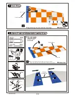
Page 2: ...t are good before gluing to defective parts during assembly Warranty will not cover any parts modified by customer Symbols used throughout this instruction manual comprise of the following Read through the manual before you begin so you will have an overall idea of what to do 1 2 3 P 1 Cut off shaded portion Ensure smooth non binding movement while assembling Apply instant glue C A glue super glue...

Page 3: ...3xD7mm 1 pc BELLY PAN 1 pc 16 DECALS A341 DEC 1 set 1 MAIN WING 1 pair 2 PUSHROD Ø1 8x85mm w Threads For Aileron 2 pcs TRI HORN PL4111221 2 sets SCREW PB2x16mm 4 pcs SCREW PB2x12mm 2 pcs SCREW PWA2 3x8mm 8 pcs CLEVIS PL4112103 2 pcs FUEL TUBE D6x5mm 4 pcs STRAPER PL4112102 2 pcs PLYWOOD 2x68x73mm Aileron Servo Cover 1 pair BALSA 8x16x16mm For Aileron Servo Stand 4 pcs MAIN LANDING GEAR COVERS 1 pa...

Page 4: ...D6x5mm PB2x16mm PB2x12mm Clevis Tri horn M3 x 14mm Pushrod Ø1 8x85mm Fuel Tube D6x5mm PB2x12mm Screw 2 PWA2 3x8mm Screw 8 PWA2 3x8mm 1 5mm Servo wire Wing Tube Ø16x456mm Apply instant type CA glue to both sides of each hinge 4 8V 6 0V operation only higher voltage will burn out the retract motor Electric retract wire PWA2 3x8mm Bottom View Bottom View Balsa 8x16x16mm Make a slot into the hatch for...

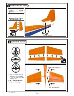
Page 5: ...es of each hinge Stabilizer Tube Ø5x134 5mm Stabilizer Tube Ø6x234mm Stabilizer Elevator 4 Apply instant type CA glue to both sides of each hinge Temporary install the main wing adjust leveling of the stabilizer to make it as parallel to the main wing as possible Stabilizer Main Wing B B B B M4x12mm Screw 3 ...

Page 6: ... Ø1mm pilot holes for World Models horn are pre drilled Please look for pin hole marks at under side of control surfaces PB2x12mm Fuel Tube D6x5mm Pushrod Ø1 8x480mm Clevis Tri horn M3 x 22mm Ø1mm pilot holes for World Models horn are pre drilled Please look for pin hole marks at side of control surfaces 2 1mm Collar PA3x14mm 3mm set screw 1 5mm PM2x10mm Screw 1 2 1mm Collar 1 Bottom View Bottom V...

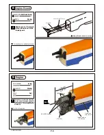
Page 7: ...ts are off centered to keep the spinner at the fuselage axis Engine 9 PM3 5x30mm Screw d3 5xD8mm Washer 4 8 8 M3 5 Nut Throttle Pushwire Ø1 2x620mm Plastic Tube d2xD3x460mm PM3 5x30mm d3 5xD8 Washer M3 5 Nut Illustration is for inverted mounting You can mount the engine upright or side ways simply by rotation the engine mount Thrust angles will not be affected 129mm 5 08 in For short engines ...

Page 8: ...e grommet to the cowling then apply screw d1 5xD6 5mm Grommet Cowling Fuselage PWA2 6x12mm PWA2 6x12mm Screw 4 d1 5xD6 5mm Silicon Grommets 4 Silicon Grommets PWA2 6x12mm Spinner Fuel Tank 10 Front Cable Tie 1 5x5x400mm Fuel Tank 500CC Bottom View ...

Page 9: ...d arrange the servo as shown in the diagram Elevator Servo Pushrod Connector J1 Pushrod Ø1 8x85mm J1 J2 Servo Set 12 Throttle Pushwire 3x3mm Set Screw Washer 2mm Washer 2mm M2 Nut Throttle Servo 1 5mm Please refer to the attached sheet for linkage connector installation 3x3mm Set Screw M2 Nut Linkage Connector 1 1 1 2 2mm Washer PWA2 6x8mm Balsa 3x71x104mm PWA2 6x8mm Screw 1 Bottom View Bottom Vie...

Page 10: ...0mm Screw d4xD15mm Washer 2 4 HM4x35mm Screw 2 Belly Pan 15 P 9 Main wing 14 HM4x60mm PM3x13mm HM4x35mm d4xD15 Washer d3xD7 Washer Belly Pan d4xD15 Washer Completed PM3x13mm Screw d3xD7mm Washer 1 1 Bottom View Bottom View ...

Page 11: ...A345PO32021803 P 10 Wing Setting Decals 16 A B C A B C A A B B C C ...

Page 12: ... according to your personal preference 5 0 in http www theworldmodels com para instruction instructionManuals php The ideal C G position is 127mm 5 0 in behind the leading edge measured at where the wing meets the fuselage In order to obtain the C G specified add weight to the fuselage or move the battery position Check the C G before flying If you are racing the Strega over 100 mph move C G forwa...

Page 13: ...mperature until the wrinkles are gone Too hot an iron may damage the covering Don t use hot iron near the seams or edges hot iron will melt the glue and shrink the covering at the same time causing the seams to pull away Check and re tighten up all factory assembled screws use thread locker if necessary is specially designed to be powered by 2 stroke 0 46 engine or In fact over powered engine may ...

Page 14: ...ing product news and free upgrade parts when applicable Please fill in the following and send to AirBorne Models 4749 K Bennett Drive Livermore CA 94551 USA 1 Name ______________________________________________ 2 Address ____________________________________________ 3 Phone ____________________ E mail __________________ 4 Model ______________________________________________ Wing QC __________ Fusel...

Page 15: ...e of the actual cutting of the pre painted cowling Usage of the transparent 3D template Simply cut the transparent 3D template to fit your engine and exhaust pipe then slide onto the actual cowling and use as template to mark the openings required for final cutting 1 2 3 4 ...

Page 16: ...A345PO32021803 ...

Reviews: