The SET-UP menus
There are 13 setup menus. A setup menu is meant to control the operation of the SPRINGin general. You can select these
menu’s by pressing [next menu] or [previous menu] repeatedly under SETUP.
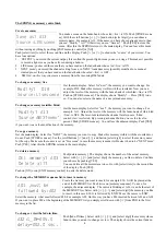
Soft patch menu-1: Patching a CONTROL channel proportional on one or more DMX channels
Repeat pressing [next menu] or [previous menu] till you see the adjacent menu..
On the upper line you can select a control channel with the buttons [select digit],
[<<] or [>>]. To select a control channel quickly: push the corresponding fader-
button. The second line shows you the DMX channel(s) on which there is made a
patch. In case of more then one patch the numbers will be displayed in a continue
chase. In the right under corner you see which percentage of the control channel value will be send trough the displayed
DMX channel. This is called the proportionality of the patch. You can remove a patch by pressing [NO]. You can create a
patch by moving the cursor to “DMXch”, selecting the desired channel number and pressing [YES]. If the display shows
“DMXch---“ there is no patch at all for the selected control channel.
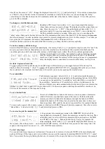
Soft patch menu-2: Testing a DMX channel and creating a patch to a Control channel
Repeat pressing [next menu] or [previous menu] till you see the adjacent menu.
On the upper line you can select a DMX channel with the buttons [select digit],
[<<] or [>>]. By pressing [YES] the data on that channel goed ‘full’. So you can
check which device on stage is driven by this DMX channel. Searching the
channel number for a particular device goes easily by scrolling the DMX channel
number with [<<] or [>>] while pressing [YES] and watching the devices. After you have found the DMX channel you
make a patch to the desired control channel by moving the cursor to the second line and selecting that control channel and
pressing [YES]. To select a control channel quickly: push the corresponding fader-button. You remove a patch by pressing
[NO].
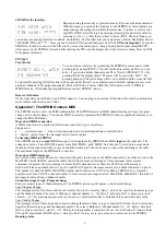
Soft patch menu-3: RESETING, CLEARING and SHIFTING the patch table
Repeat pressing [next menu] or [previous menu] till you see the adjacent menu.
Moving the cursor to “RESET?” and pressing [YES] will create a patch from
control channel-N on DMX channel-N with N=1,2,3, etc. Moving the cursor to
“CLEAR?” and pressing [YES] will remove any patch. Moving the cursor to
“SHIFT=000” and select a value other than 000, lets say 012, cause that the
original patch from control channel-X on DMX channel-Y will be changed in a patch from control channel-X on DMX
channel-(Y+12). The default setting is “SHIFT=000”.
Setting a control CURVE
Repeat pressing [next menu] or [previous menu] till you see the adjacent menu.
Here you select a control curve for each control channel. By choosing a curve
you can for example correct a typical non linear response of a device what is
controlled by that channel. There are 5 possibilities:
Linear
=no correction, S-
curve= correct the non linear response of halogen lamps, ‘non
-dim’
= the channel
acts like a switch (on/off), Trafo12V special correction for 12V halogen lamps with an electronic transformer, 'non-fade' =
means a level change will be stepwise. Procedure: select a control channel number by pressing [select digit], [<<] or [>>]
or push the corresponding fader-button. Move the cursor to the curve name and select by pressing [<<] or [>>] the desired
curve. The default curve is ‘LINEAR’.
Setting the switch point for NON-dim and resetting all curve settings
Repeat pressing [next menu] or [previous menu] till you see the adjacent menu.
By pressing [<<] or [>>] you can set the level at which the value of the control
channel will be transformed in ‘full’ or ‘off’. Example: Channel-5, NON-dim is
set, NON-dim switch point is set on 20%. Lets consider the cross fade from
memory B03(level channel-5 is 0%) to B04(level channel-5 is 100%). The DMX
output for this channel will be 0% as long as the (internal) fade algorithm output a value lower then 20%. After that the
DMX output value is 100%. So if the fade time is 3[s], the switch action is 0.6[s] after the start of the cross fade.
The second line of the menu gives the possibility to set the same curve for all channels. Move the cursor by pushing [select
item] to the curve name(right under). Select by pushing [<<] or [>>] the desired curve and then press [YES].
.
Setting the DMX input mode and “hold DMX-in data on loss of signal”.
Repeat pressing [next menu] or [previous menu] till you see the adjacent menu.
Here you can choose, by pressing [<<] or [>>], what the SPRING will do with
the DMX-input data. Choosing “SCENEmode”: the input data will be seen as a
7
Ch001 patched on
DMXch001:y, 100%
Test DMXch001 ?
patch’on Ch001:y
SoftPatch:RESET?
CLEAR?,SHIFT=000
Control Curve:
Ch001 -> Linear
NONdim:ON ->050%
all Ch.->Linear?
DMXin:MERGEmode_
Hold Data Set=y


