LOCKING the interface
Repeat pressing [next menu] or [previous menu] till you see the adjacent menu.
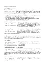
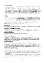
With this menu you can lock the interface of the SPRING. In this condition you
cannot change the settings and modify the memories. You have to select a four
digit PIN CODE: select the digit by pressing [select digit] and select a value by
pressing [<<] or [>>]. After that you have to press [YES]. The only things you
can do now are playing memories or unlock the interface. For the latter case you can press any button. The display shows
“LOCKED! PIN code: ****”. Now you can fill in the PIN code and then press on [YES].
PIN code forgotten?
In case the
SPRING is locked you can view the PIN code by: removing mains power, keep pressing button [next menu](SETUP)
while power on the SPRING. Attention after showing the PIN code the display shows the total reset menu. Press on [NO]
for bypasses this menu.
FINALLY
Total Re-Set
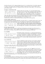
You can create a total reset by connecting the SPRING to mains power while
pressing [next menu](SETUP). You will see the adjacent menu. Here you can
select, if you wish, another channel count:24 or 72(only SPRING-V3 72). By
pressing [YES] the display shows “Memory will be overwrite!, Sure?”. By
pressing again on [YES] all settings will be set to default and the scene list will
be cleared. By pressing [NO] all actions will be canceled followed by a normal power-on. Default settings are: reset soft
patch, all channels 100% proportional patch, Patch shift=000, all curves LINEAR, NON-dim on at 50%, DMX in:
MERGE-mode, NO channel-pairing and Remote control=PRESET selector.
Remote GO button
On the right side you will find a 5-pole DIN connector. You can plug in an external GO-button; this must be a momentary
make contact connected on pin 2 and 3.
Appendix-1: The SPRING versus MIDI
The SPRING can be a slave in a MIDI configuration. The SPRING reacts on MIDI channel messages of type ‘program
change’ and ‘control change’. You can use MIDI to remotely command the SPRING to fade-in a particular memory or to
change the MASTER fader.
More about MIDI-connection
A MIDI-connection is a digital serial electronic connection, type current loop.
Explanation:
•
‘..... serial electronic....’: a two wired connection across which digital data is send bit by bit.
•
‘digital....current loop’: the messages exist of current pulses.
Connecting MIDI to SPRING
The SPRING can only
accept
MIDI messages. For that purpose the SPRING has a MIDI
input
on the right side. The
connector used is a 5-pin DIN (180 degree) male. Pin4=MIDI+, pin5=MIDI-. Note that pin 1, 2 and 3 are not used and
should be left unconnected. Only in case of a shielded cable, pin 2 should be used to connect the shielding of the cable.
The maximum length of the MIDI cable is 6 meters.
More about MIDI-messages
In a system where several devices are connected with each other by means of a MIDI-connection, one of the devices is the
MASTER. This MASTER controls the others (SLAVES) by means of messages. These messages imply several
commands. In general not every message is meant for all connected slaves; there are SLAVE specific messages.
Each SLAVE has a number between 1 up to 16 and SLAVE specific messages involve also a number between 1 up to 16.
This number is called the MIDI CHANNEL number and in this sense a SLAVE is called a CHANNEL. So it must be
possible to set for a SLAVE a channel number. A slave selective message is called ‘CHANNEL MESSAGE’; this kind of
messages involves always a channel number.
Channel message of type: Program change
There are several types of channel messages. The SPRING acts on type Program - and Control Change.
Case Program Change
This message exists of two bytes and is used to start a fade-in of a memory. Byte-1, status byte, specifies the message type
and the channel number. The value is Cn[hex], n=channel number (1,...16). Byte-2, data byte. Bit-7 is always zero, byte
value=0,...,127. By pressing [assign scene to] you can set which memory has to be faded in for a particular byte value.
Case Control Change
This message exists of three bytes and is used to change the master fader or to get a remote GO-button. Byte-1, status byte.
Specifies the message type and the channel number. The value is Bn[hex], n=channel number (1,...16). Byte-2, data byte.
Bit-7 is always zero, byte value=0,...,127. This byte value specifies a controller. We use: 96=GO button, 97=master fader
UP and 98=master fader DOWN. Byte-3, data byte. Bit-7 is always zero, byte value does not matter for the SPRING.
Running status
9
RESET ALL!, with
24 channels?
Set LOCK with
PIN code: ****?


